Building a compact arduino based DMX testing device
Sebastian Pohl - 5. November 2017We are currently working on a project that involves a device that reacts in a certain way to signals it gets via DMX. DMX is a protocol that is widely used for lighting and effects.
We had the option to rent a fully fledged DMX console for testing our hardware prototypes. But this would have been cost-intensive and time consuming. And i knew that the protocol itself is not the most complex thing in the world. I had the idea to build a small device that could send a DMX signal.
The concept was done very quick, here are the features i was planning for the device to have:
- stand-alone, not a usb DMX interface or something else.
- mobile, no external power required.
- display, so the user can see what value is sent on which channel.
- Intuitive interface, one dial for the adress, one for the value.
Next i started my research. I had narrowed it down to a few very simple parts that i needed to solve:
- send DMX signals.
- display stuff on an lcd.
- react to a rotary encoder.
- react to a button.
- react to a potentiometer.
I quickly decided to develope this on an arduino because it would not require much power to run and i had seen tutorials for almost everything i needed online. Here you can see how to interface to a 16×2 LCD, here is a long page about rotary encoders, the button is explained here and the potentiometer here.
The only thing i had yet to come across was an easy explanation on how to send DMX signals. I was lucky enough to stumble upon the DmxSimple Library very quick which was exactly what i was looking for. I was slightly disappointed at first because the introductory text was talking about DMX shields to use but then i saw that it mentioned a diy solution and had this link.
At this point i had my list of components:
- Arduino pro
- rotary encoder with switch
- potentiometer
- trim-potentiometer (lcd contrast)
- IC SN75176 (to generate the DMX output)
- 16×2 lcd
- xlr socket
- perfboard
- optional: bread-board
And a few resistors and wires as well as general soldering stuff. Most of the things i already had lying around, only the xlr socket and the SN75176 had to be ordered.
When everything arrived this was the test-setup on a breadboard:

The potentiometer to dial in the values is missing in this picture. I tried to plot out this setup in the fritzing software:
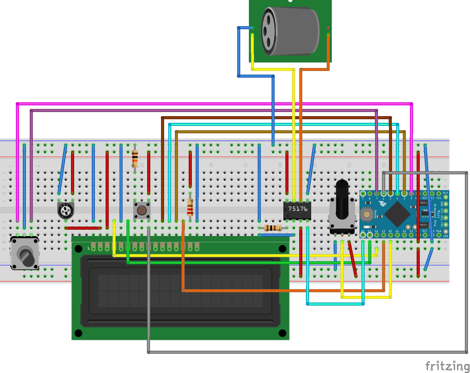
The only difference is that i had to use a separate button here because i could not find a rotary encoder module in fritzing with a built in button.
The test setup looks a little bit unorganised and wild because i started with the simplest parts like buttons and potentiometer and added everything else later. All of the examples i listed above had some basic source code on how to program it and i made a frankenstein program from all of them that runs my DMX tester:
#include <LiquidCrystal.h>
#include <DmxSimple.h>
byte tx[8] = {
B01000,
B11100,
B01000,
B01000,
B00101,
B00010,
B00101,
};
const int rs = 12, en = 11, d4 = 5, d5 = 4, d6 = 3, d7 = 13;
LiquidCrystal lcd(rs, en, d4, d5, d6, d7);
int encoder0PinA = 2;
int encoder0PinB = 7;
int potPin = 0;
int potPos;
int switchPin = 8;
int switchState = 0;
int encoder0Pos = 1;
int encoder0PinALast = LOW;
int n = LOW;
void doEncoder() {
if (digitalRead(encoder0PinA) == digitalRead(encoder0PinB)) {
encoder0Pos++;
} else {
encoder0Pos--;
}
}
void setup() {
DmxSimple.usePin(10);
DmxSimple.maxChannel(512);
lcd.createChar(0, tx);
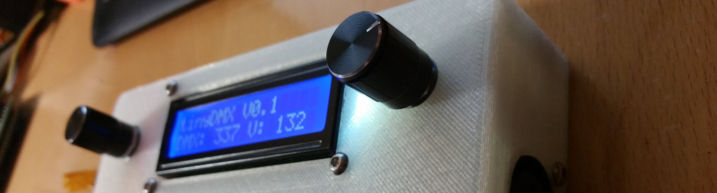
lcd.begin(16, 2);
lcd.print("tinyDMX V0.1");
pinMode (encoder0PinA, INPUT_PULLUP);
pinMode (encoder0PinB, INPUT_PULLUP);
pinMode (switchPin, INPUT);
attachInterrupt(0, doEncoder, FALLING);
}
String formatNumber ( int number ) {
if ( number < 10 ) {
return "00" + String(number);
}
if ( number < 100 ) {
return "0" + String(number);
}
return String(number);
}
void loop() {
if ( encoder0Pos > 512 ) {
encoder0Pos = encoder0Pos - 512;
}
if ( encoder0Pos < 1 ) {
encoder0Pos += 512;
}
potPos = analogRead(potPin);
switchState = digitalRead(switchPin);
if ( switchState == HIGH ) {
lcd.setCursor(14, 0);
lcd.write(byte(0));
DmxSimple.write(encoder0Pos, map(potPos, 3, 1020, 0, 255));
} else {
lcd.setCursor(14, 0);
lcd.print(" ");
}
lcd.setCursor(0, 1);
lcd.print( "DMX: " + formatNumber(encoder0Pos) + " V: " + formatNumber(map(potPos, 3, 1020, 0, 255)));
}
And i was more than surprised to see that it worked. The code above is my unaltered test-code. The reason why i do not show a polished, fine-tuned version is because i want everyone to be able to fully understand what is going on and to see how i puzzled everything together. Let me go into details on some of it:
void setup() {

  DmxSimple.usePin(10);
  DmxSimple.maxChannel(512);

  lcd.createChar(0, tx);
  lcd.begin(16, 2);
  lcd.print("tinyDMX V0.1");

  pinMode (encoder0PinA, INPUT_PULLUP);
  pinMode (encoder0PinB, INPUT_PULLUP);
  pinMode (switchPin, INPUT);

 attachInterrupt(0, doEncoder, FALLING);

}
The setup function merely initializes everything i am going to use. It starts the DmxSimple, the lcd and sets up the pins i will use for input. Something i want to point out are these lines:
pinMode (encoder0PinA, INPUT_PULLUP);
pinMode (encoder0PinB, INPUT_PULLUP);
I initially used a rotary encoder module that came with a kit and it already had pullup resistors built in, but when i switched to a bare encoder i got lots of false readings and missed steps as well as wrong detection of the direction. And instead of trying to solder resistors to the encoder i simply enabled the arduinos internal ones. The other thing that helped a lot was to do some hardware debouncing by adding two little capacitors and by switching from reading the values inside the loop function to do it by interrupt (more on interrupts here). Please be aware that interrupts only work on certain pins!
void loop() {

  if ( encoder0Pos > 512 ) {
    encoder0Pos = encoder0Pos - 512;
  }

  if ( encoder0Pos < 1 ) {
    encoder0Pos += 512;
  }

  potPos = analogRead(potPin);
  switchState = digitalRead(switchPin);

  if ( switchState == HIGH ) {
    lcd.setCursor(14, 0);
    lcd.write(byte(0));
    DmxSimple.write(encoder0Pos, map(potPos, 3, 1020, 0, 255));
  } else {
    lcd.setCursor(14, 0);
    lcd.print(" ");

  }

  lcd.setCursor(0, 1);
  lcd.print( "DMX: " + formatNumber(encoder0Pos) + " V: " + formatNumber(map(potPos, 3, 1020, 0, 255)));

}
The loop is where all the interesting stuff happens. Because i use interrupts to read the encoder i only have to do some overflow handling with the encoder position so i only get values between 1 and 512 to use as DMX addresses. Next i read the switch and the potentiometer. When the switch is pressed the value of the potentiometer is send as a DMX signal to the currently selected address.
DmxSimple.write(encoder0Pos, map(potPos, 3, 1020, 0, 255));
The use of map here is to remap the value of the potentiometer, which ranges from 0 to 1023, to the range the DMX protocoll allows, which is 0 to 255. Everything else in the loop is lcd stuff.
With the breadboard setup and the code shown above i had a device on which i could dial in an address with a rotary encoder and a value with a potentiometer and then send it when i press the encoder button.
The next step was to transfer this whole thing to a perfboard and put it into a 3d printed case. This is what i came up with:

The nice pinheader-plug on the left side is because i had no power switch left, as soon as it gets here, it will go into the left side of the case.
Maybe a little bit more interesting are the guts:
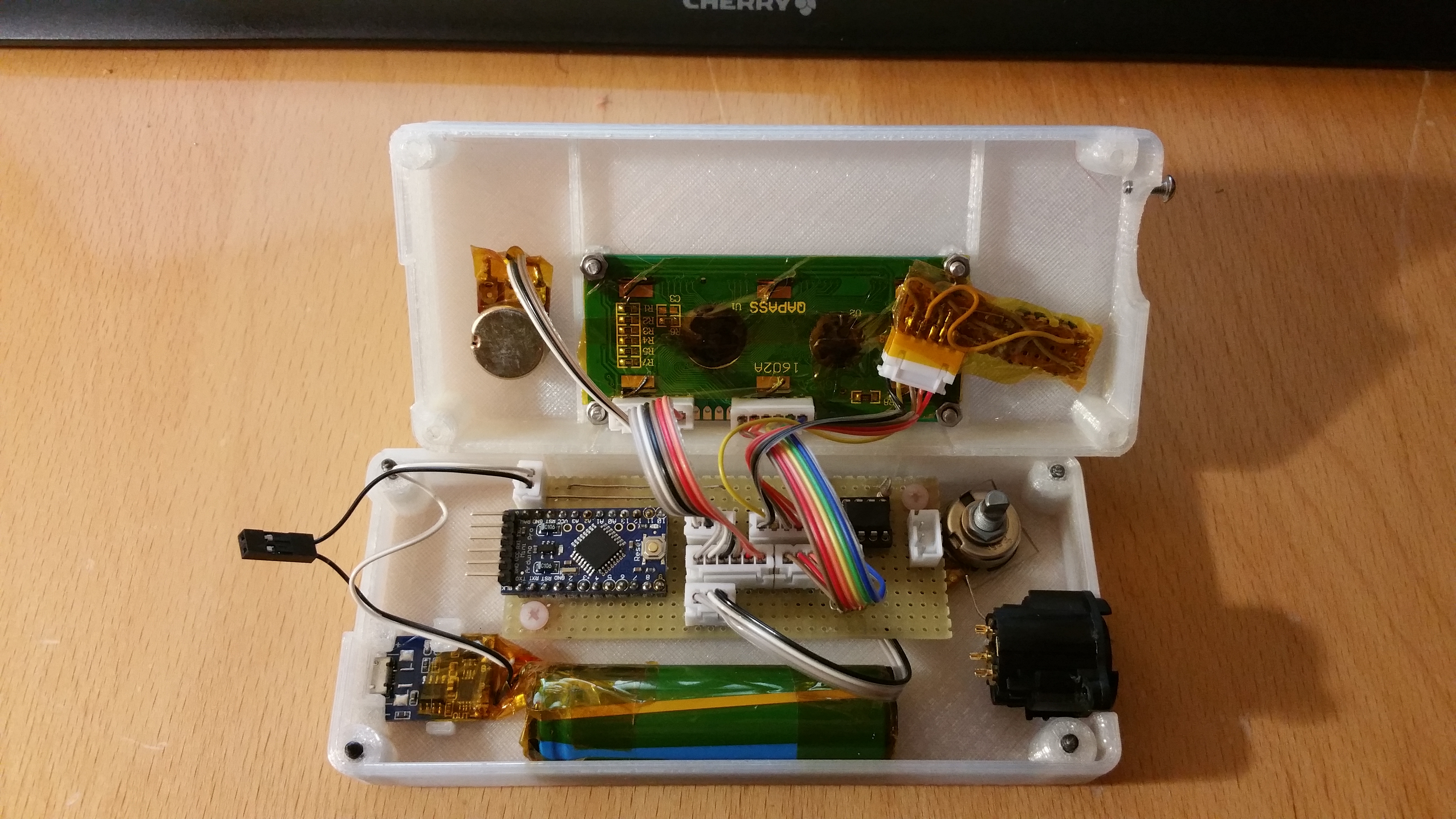
Here you can see that i added a 18650 cell (from an old powerbank) to power everything. It is connected to a usb charging board so i can reacharge it with any usb power supply. Also there is a 3-pin xlr socket that is not yet attached to the 3-pin jst header on the right side of the board. I am just waiting for a few more parts to finish everything up ( And maybe change to the 5-pin socket ).
Now i have a nice portable, more or less compact, DMX tester!