Naked GoPro 9 – Decasing and Recasing
Sebastian Pohl - 31. Januar 2022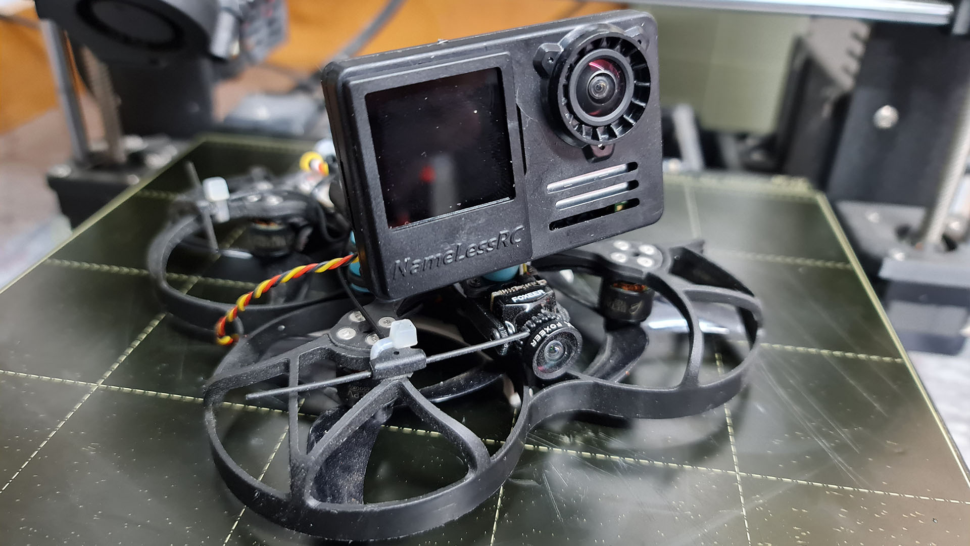
I have been a hobbyist drone pilot for a few years now. I am not the best pilot in the world but i am proficient enough in handling FPV-Dones to get my share of fun.
One of the main aspects that drew me to the hobby is the tinkering with electronics. And although i usually take the cheapest routes, because it still is a hobby and not my day-job, i get to play around with cool stuff from time to time. If i use an action cam to record in-flight footage it usually is some cheap knock-off model and not something expensive like an original GoPro.
A few days ago a friend asked if i could help him out with building one or more „naked GoPro“ cameras. This means removing all the components of an original GoPro from their case and putting them into some lightweight 3d-printed or injection moulded case. The point of this is to use those stripped GoPros on small drones which and capture great looking footage. Depending on the excat model it is possible to reduce the weight by around 100g. And that makes a huge difference if the overall weight of the drone, including the camera and battery, should be below 250 gr. Lower weight means longer flight times and less stress on the components.
Over the generations of GoPros it became increasingly difficult to remove them from their case. I do own one GoPro 6 and it was fairly easy to strip it. As i researched how to remove the case of a GoPro 9 i found several videos that showed the process involving hack-saws or similar brutal instruments.
I was pretty sure that there had to be an easier way. Maybe not totally reversible but at least not leaving everything in bits and pieces.
Before you start, consider installing GoPro Labs as it brings a QR code setting feature which makes it a lot easier to set up and configure the camera in its stripped form!
Cracking open the case
When the GoPro 9 arrived i was eager to start and forgot to take a picture in its original state.
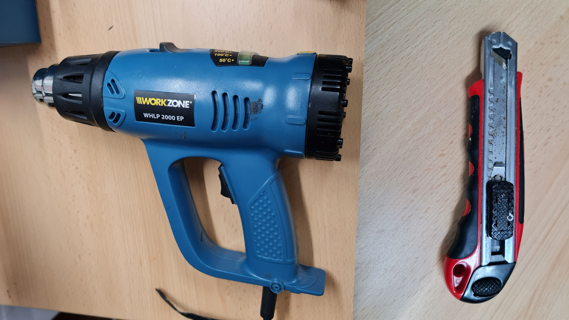
I immediately started with just two tools: A heatgun and a box cutter. I was convinced that the parts of the case were glued together and that i could soften up the glue with heat.

And to my surprise this worked really well! And it looked a lot less brutal than the instuctions which used a hacksaw or a serrated knife. It almost looks like it could be possible to glue it back together.
I used the heat gun at a moderate setting to heat up one edge at a time and then used the knife, starting at a corner to carefully cut into the visible seam. If you try to do this, please be very careful! You will need some moderate force with the knife and a slip might end up with you stabbing yourself in the hand. Also try not to heat the screen too much, they dont really like that and might break or get discoloured.
The whole process only took a few minutes and the back was almost free.
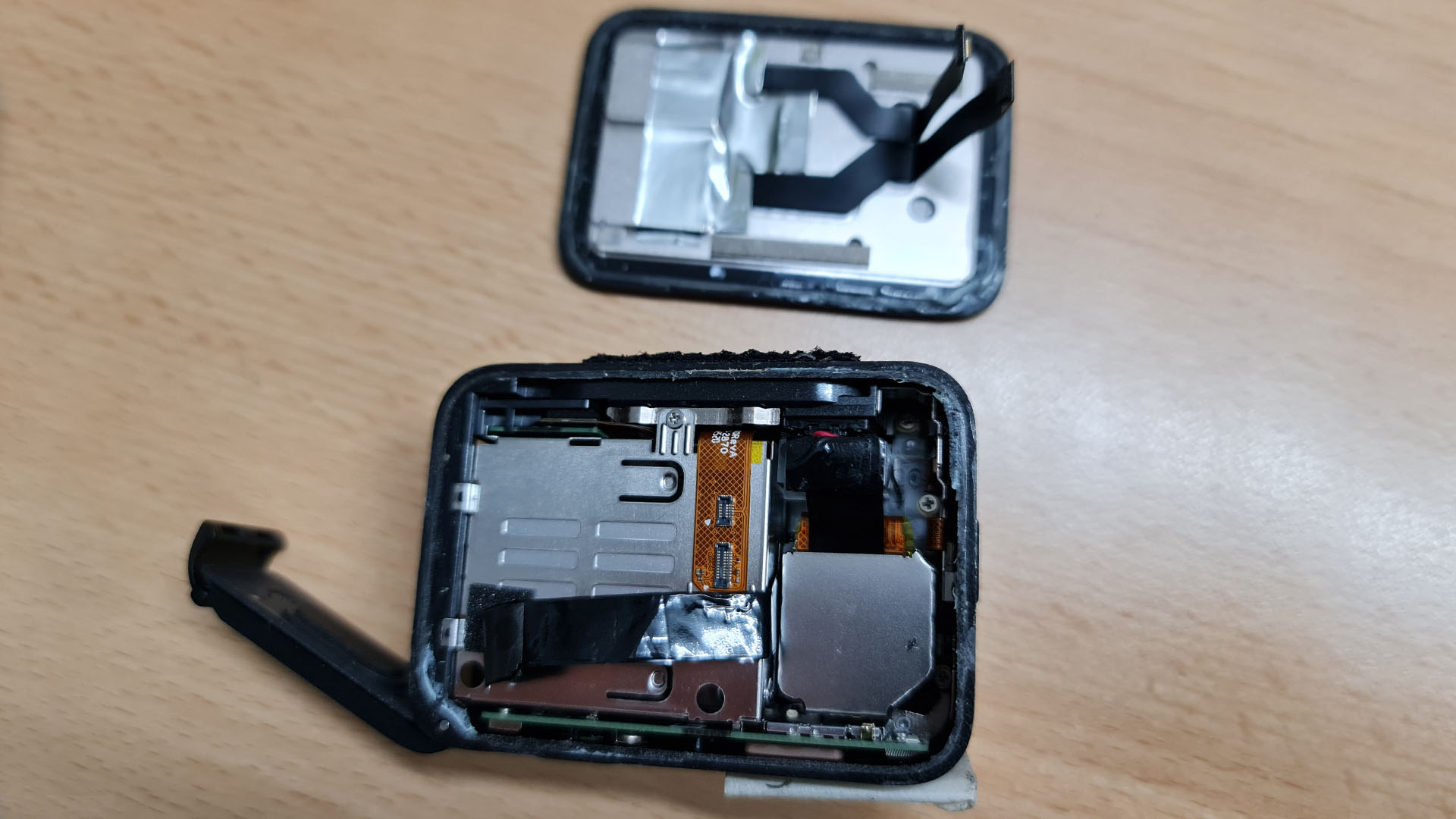
It is held on by two ribbon cables that easily pop out off their connectors and two black strips which might be graphite filled thermal conducters like they are used in modern mobile phones, but that is only a guess. Carefully remove those from the metal of the back element and put it to the side.
For the further process of removing all the guts you will need the following tools:
- PH0 Screwdriver
- PH00 Screwdriver
- TX5 Screwdriver
- Plastic prying tool
Removing the battery housing
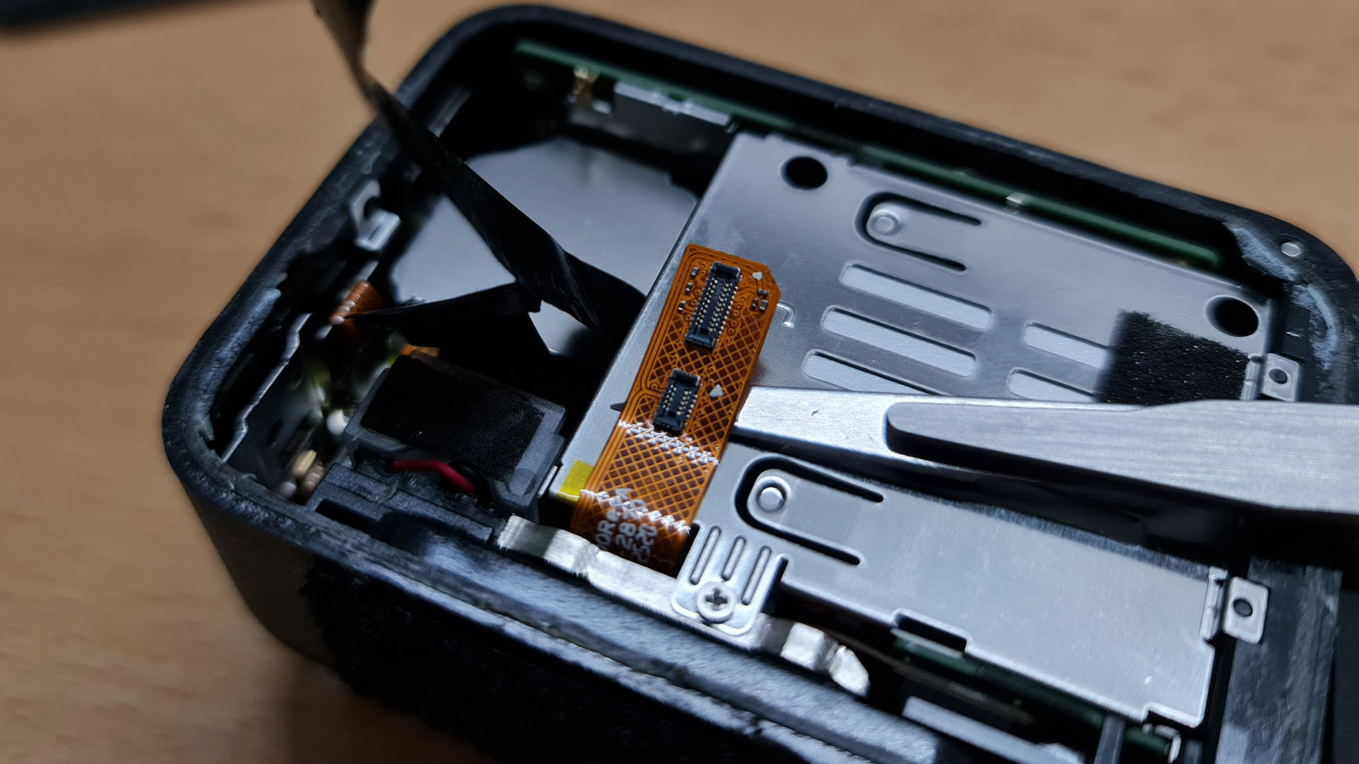
The next step will be removing the battery housing. As you can see, the connectors for the back screen are glued to the metal casing. Carefully pry the flexible connector strip off.

The casing itself is held on by three screws. Two of them are accessible through the two holes at the top edge and one is visible at the lower edge.
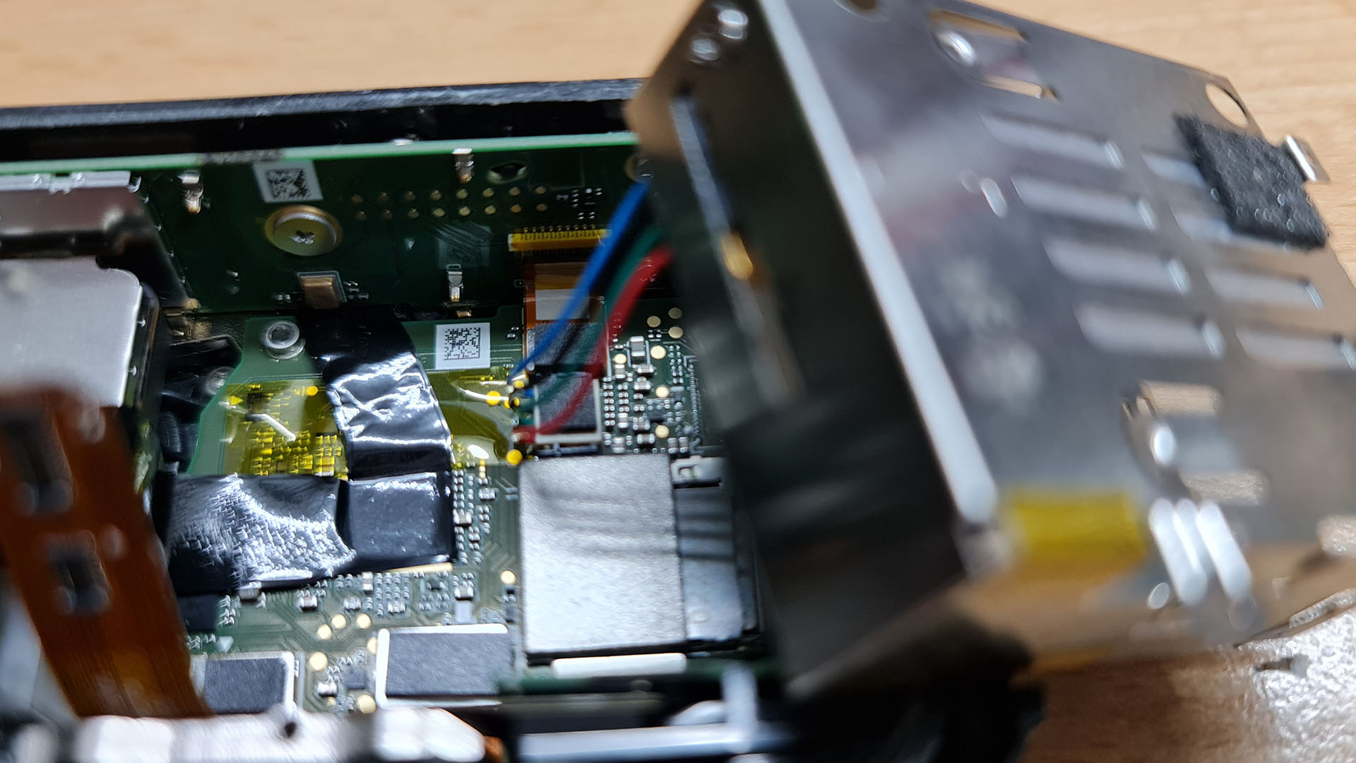
Dont yank on the battery compartment too hard because it still is attached to the mainboard with a cable. But you can use a plastic prying tool to lift it from its socket.
Now you can put the battery case to the side.
Removing the USB connector and other small parts
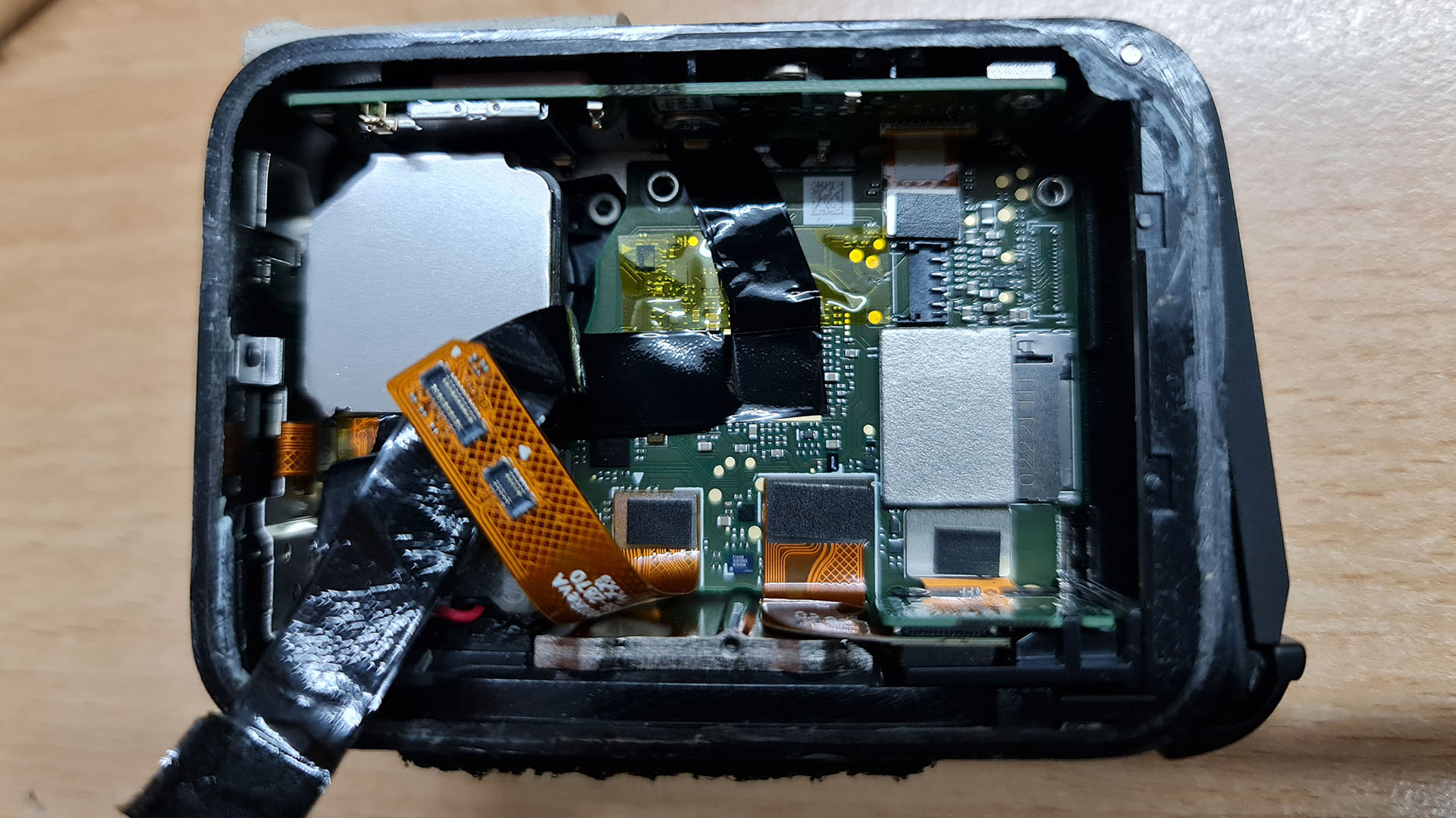
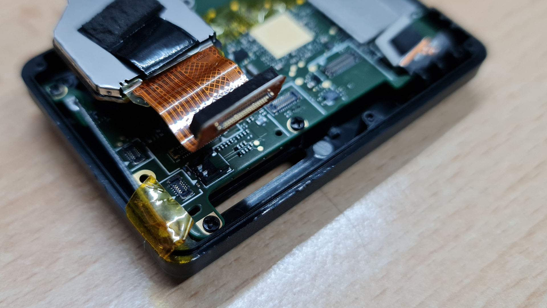
With an unobstructed view of the mainboard you can see that the ribbon which holds the two connectors for the backscreen is itself only attached to the mainboard with another of the same connectors. Carefully lift it from its connector and put it to the side.
Next you can remove the usb connector which is located at the bottom of the camera on the right side. Disconnect the flex cable first and then carefully push it to the left to free it from its locked position.
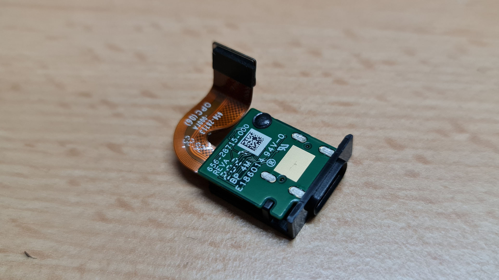
You can also put that element to the side.
At this step i was wondering what the course would be and i decided to take out the transparent element in the bottom left corner. I am not quite sure what its purpose is but it is held in place by two screws on the left side between it and the side of the camera.
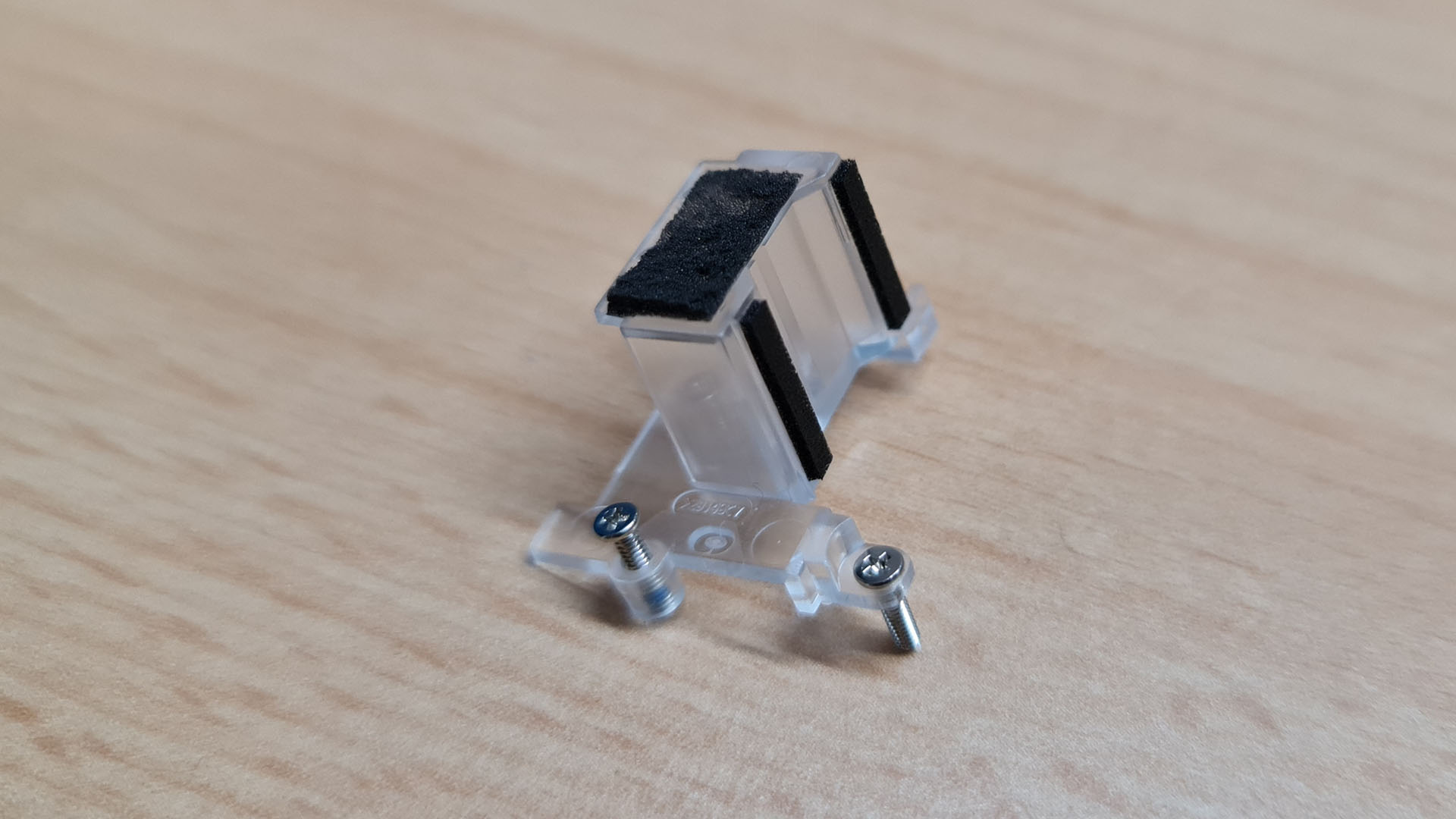
Unscrew it, take it out and put it in a safe spot.
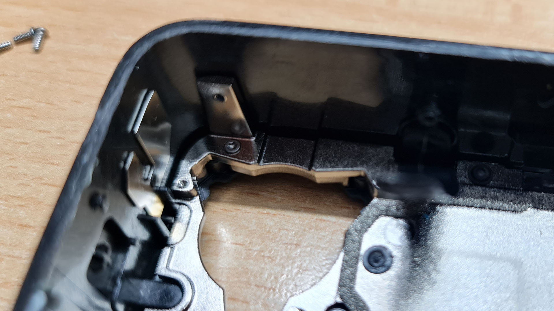
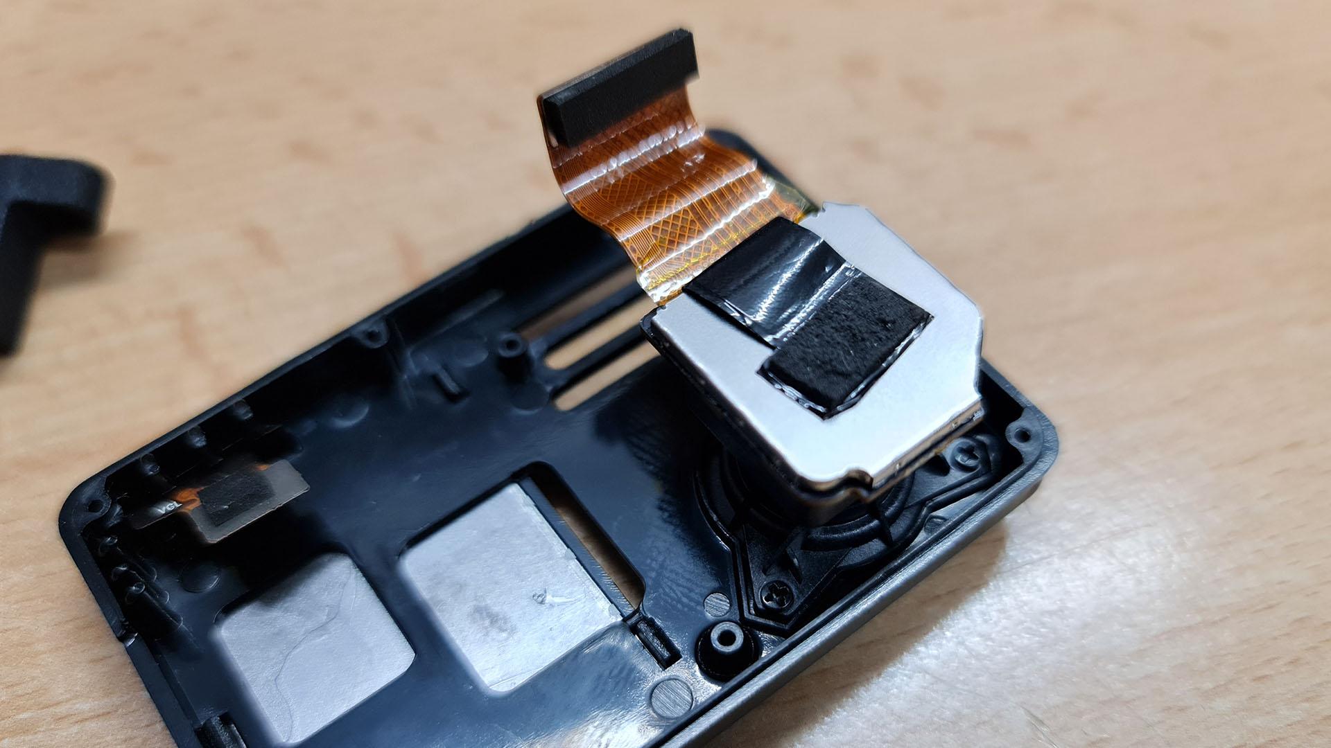
Removing the lens module
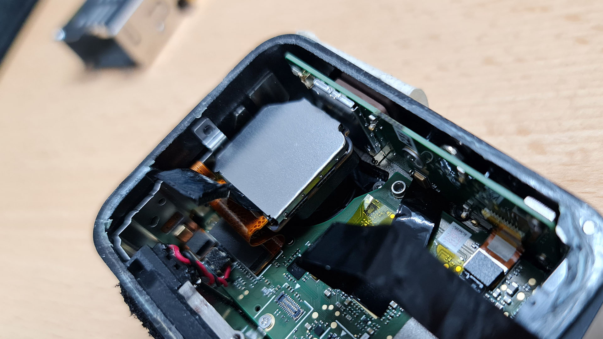
Taking a look around, the lens module seemed to be the next logic step. It is secured by three TX5 screws (Take a look at the next pictures to see their exact location.). One on the top left, one on the top right and one in the bottom center of the module. The two at the top are easy to reach but for the first one you will have to unplug the ribbon cable and move it up and fold it over the lens module to have enough room to unscrew the hidden screw.

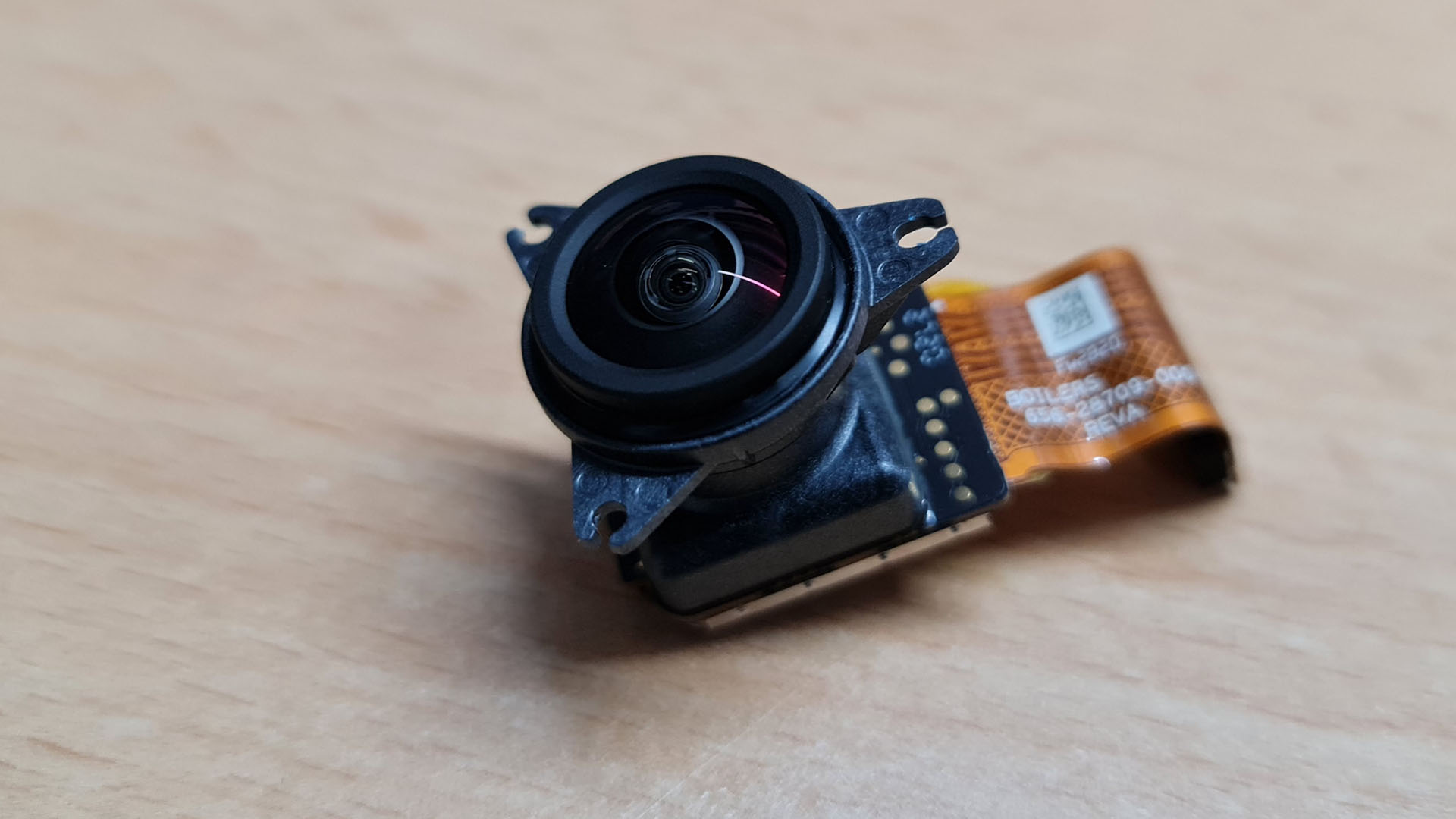
If you removed all three screws you can take out the whole module. Be careful not to damage the ribbon cable for obvious reasons. Pull the element straight up, it will have some resistance due to a rubber seal but it will pop out.
Be especially careful when putting this aside. You dont want to scratch the lens!
Getting the mainboard out
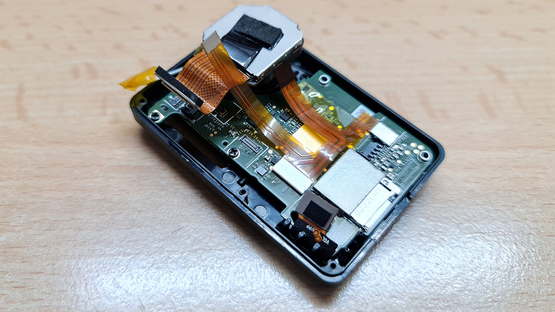
You have almost freed the mainboard! There are only a few screws left.
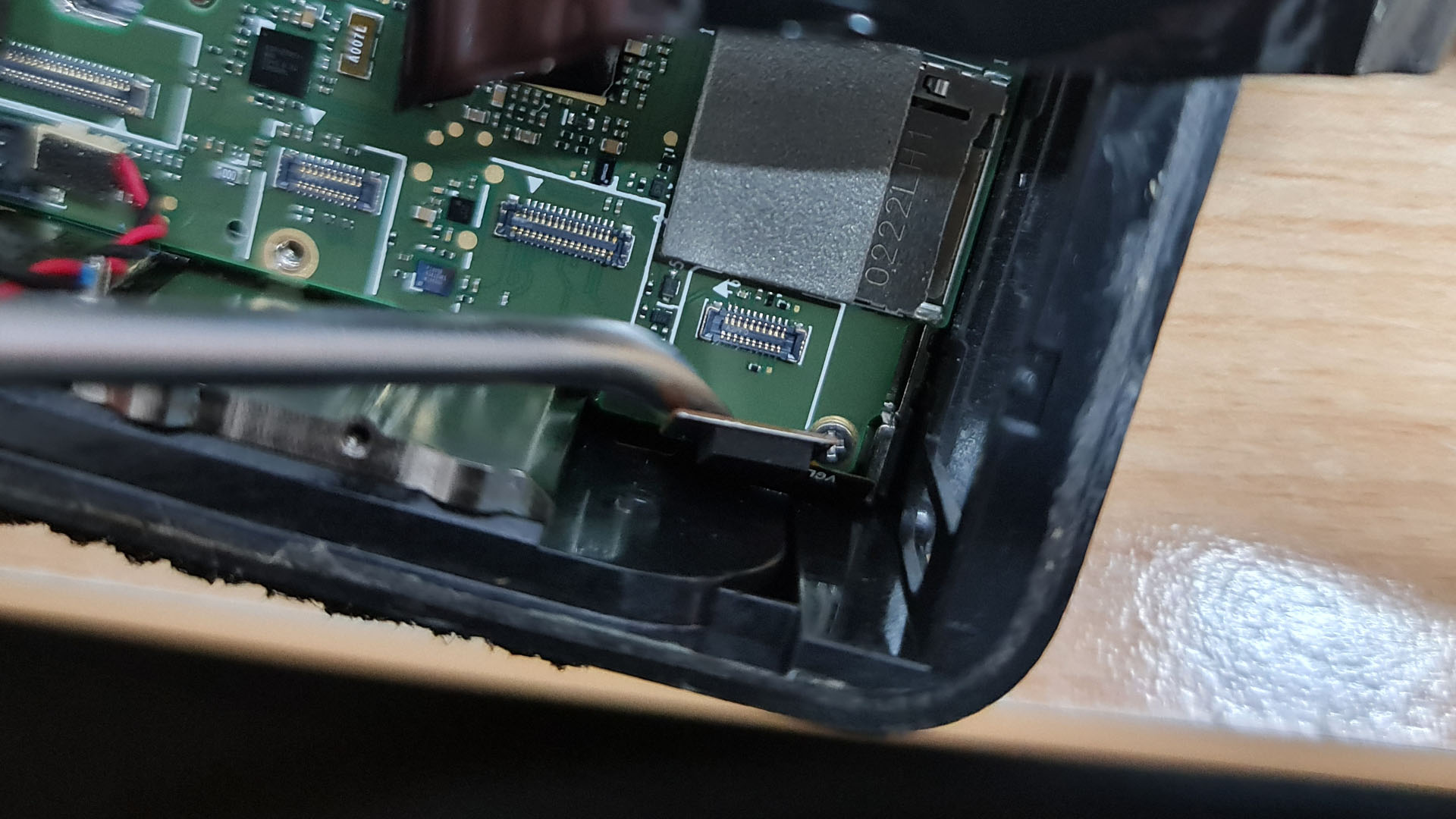
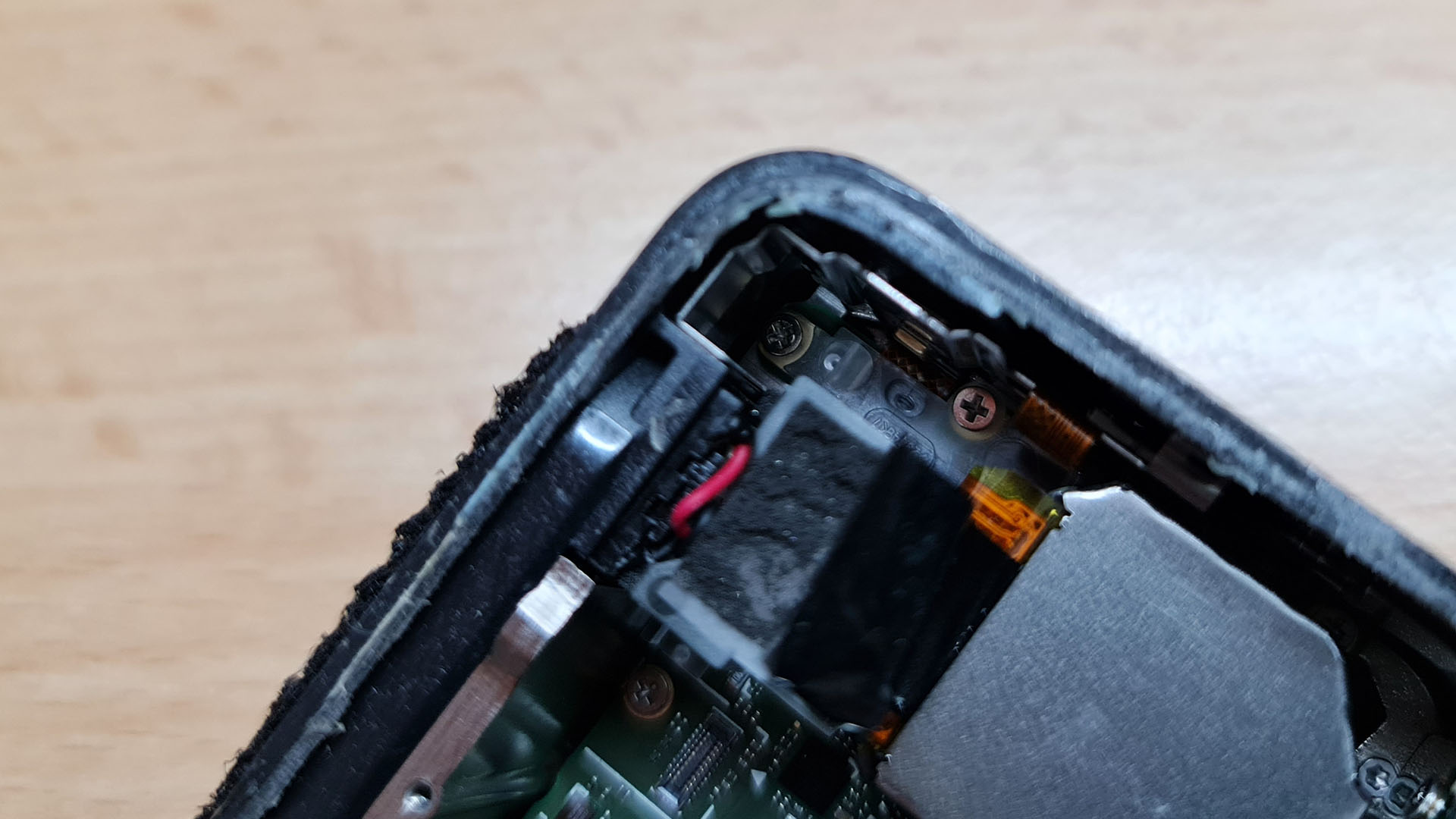
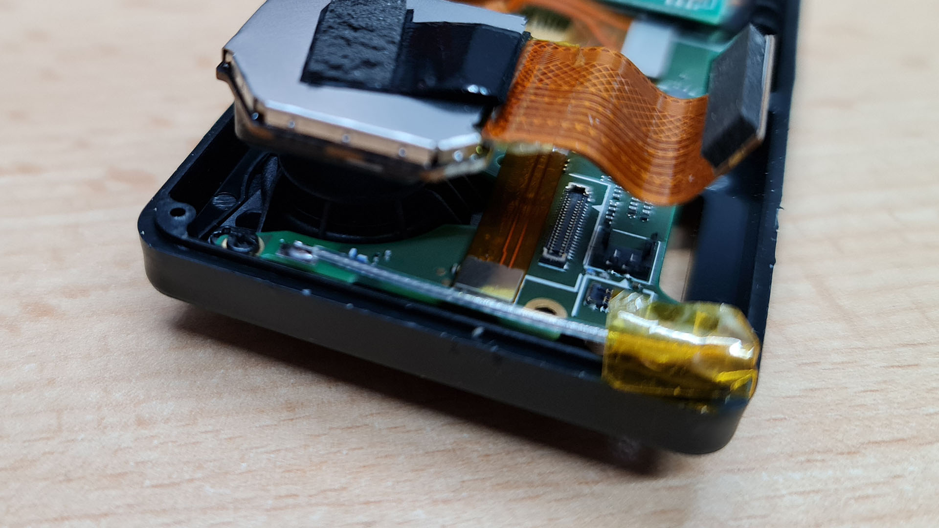
One of them is hiding under the connector for the front screens ribbon cabel, dont miss it! While you are at it, pop up all other ribbon cables that are still connected around the edges of the mainboard.
There is one at the top, for the module with the GPS and the button on top. Two are on the left for the power button and probably the microphone. Also, dont forget the speaker connector which is close to the lower right corner. With all of them removed you can carefully lift up the mainboard using a plastic prying tool. While lifting pay close attention to all the connectors to not rip any of them!

This is the mainboard in all of its glory.
Removing the other modules
If you want to use it later you can remove the three screws of the module with the GPS receiver but be aware that it is really complicated to reach them and they are easily stripped.
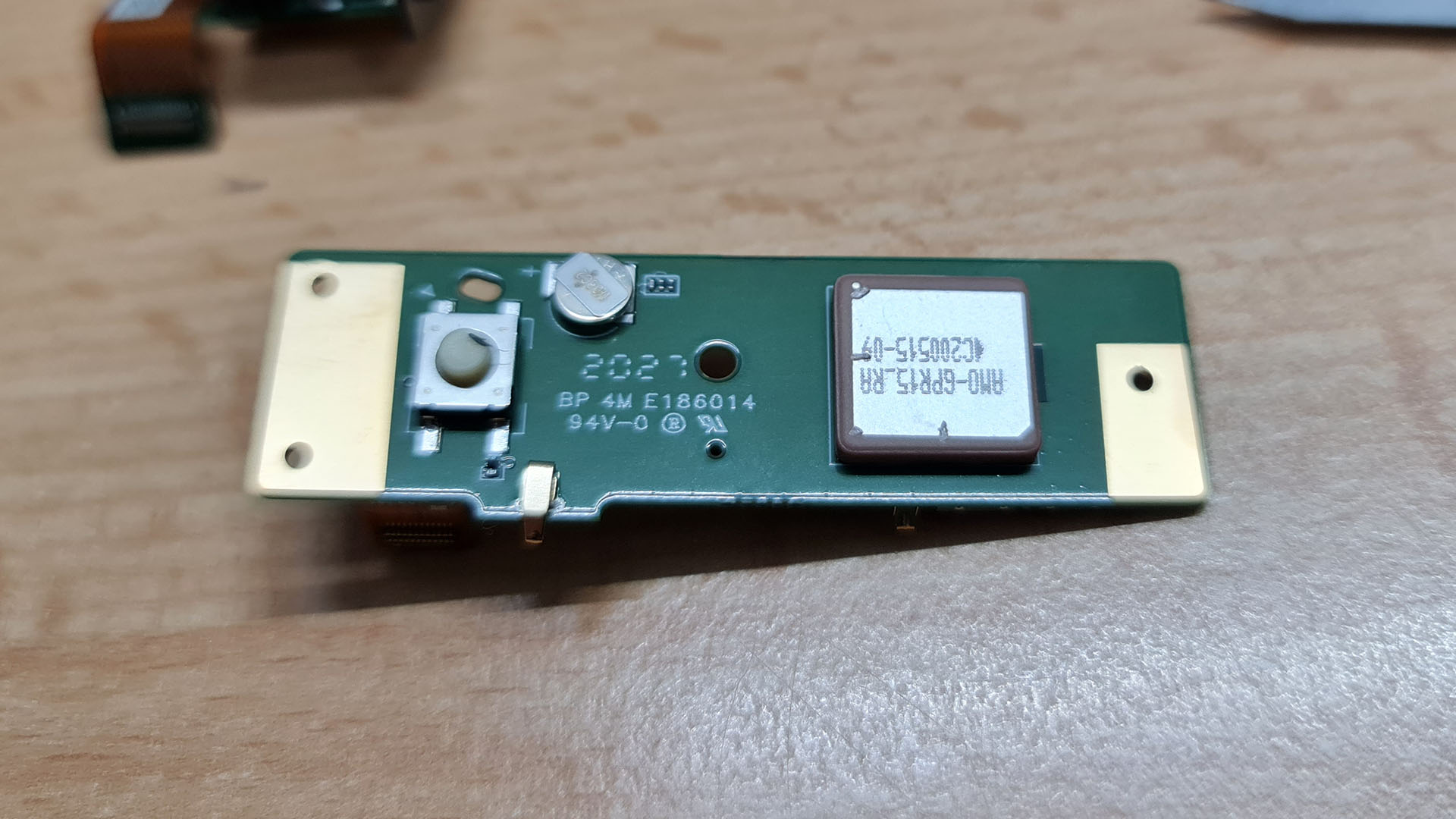
This is the module.
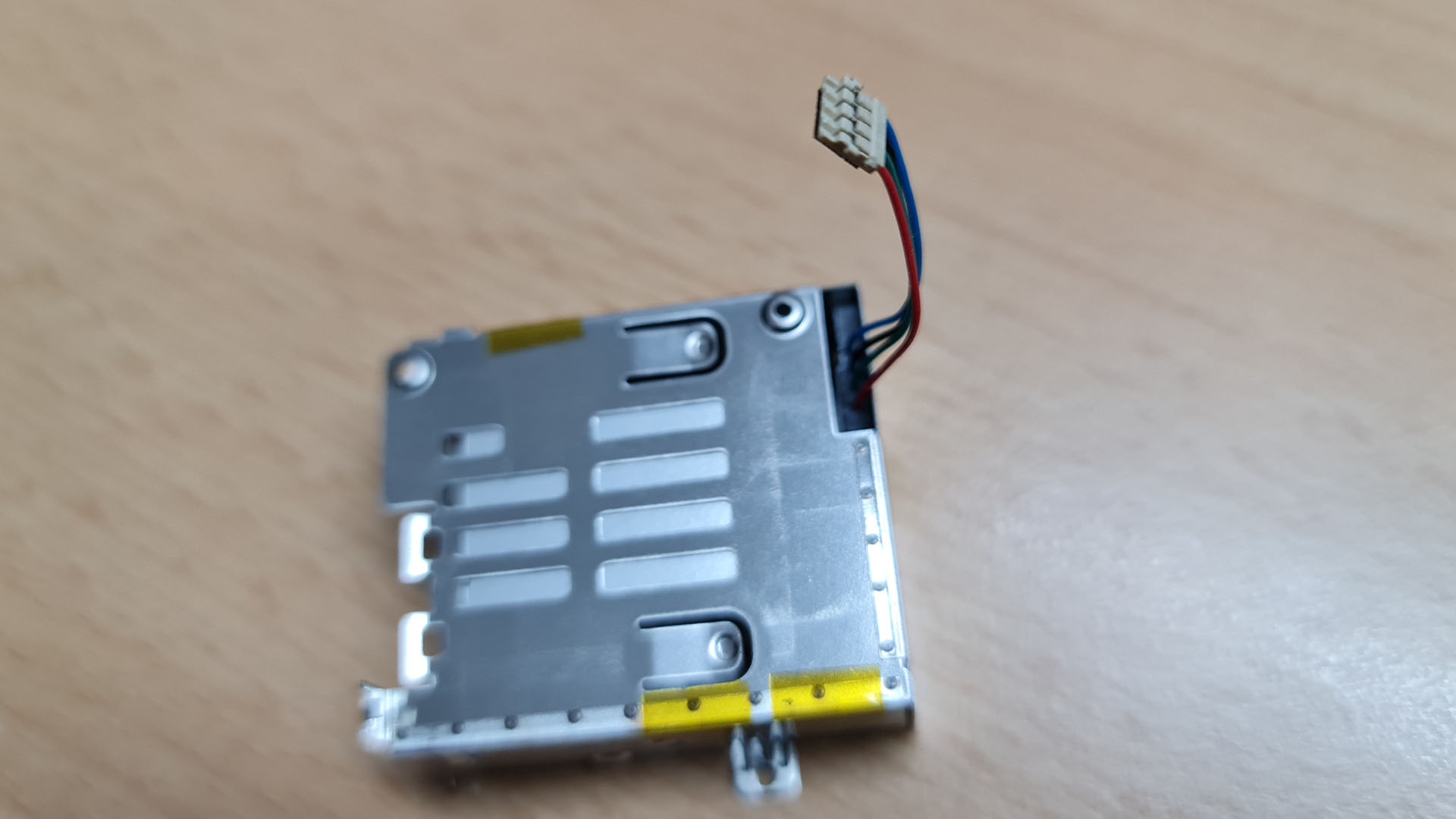
To make testing easier it might be a good idea to also remove the power button. Luckily the metal shield that it is glued to is only held in by two tiny plastic pins. Some light prying will pop it right off. Be aware that this is a possibly irreversible step!
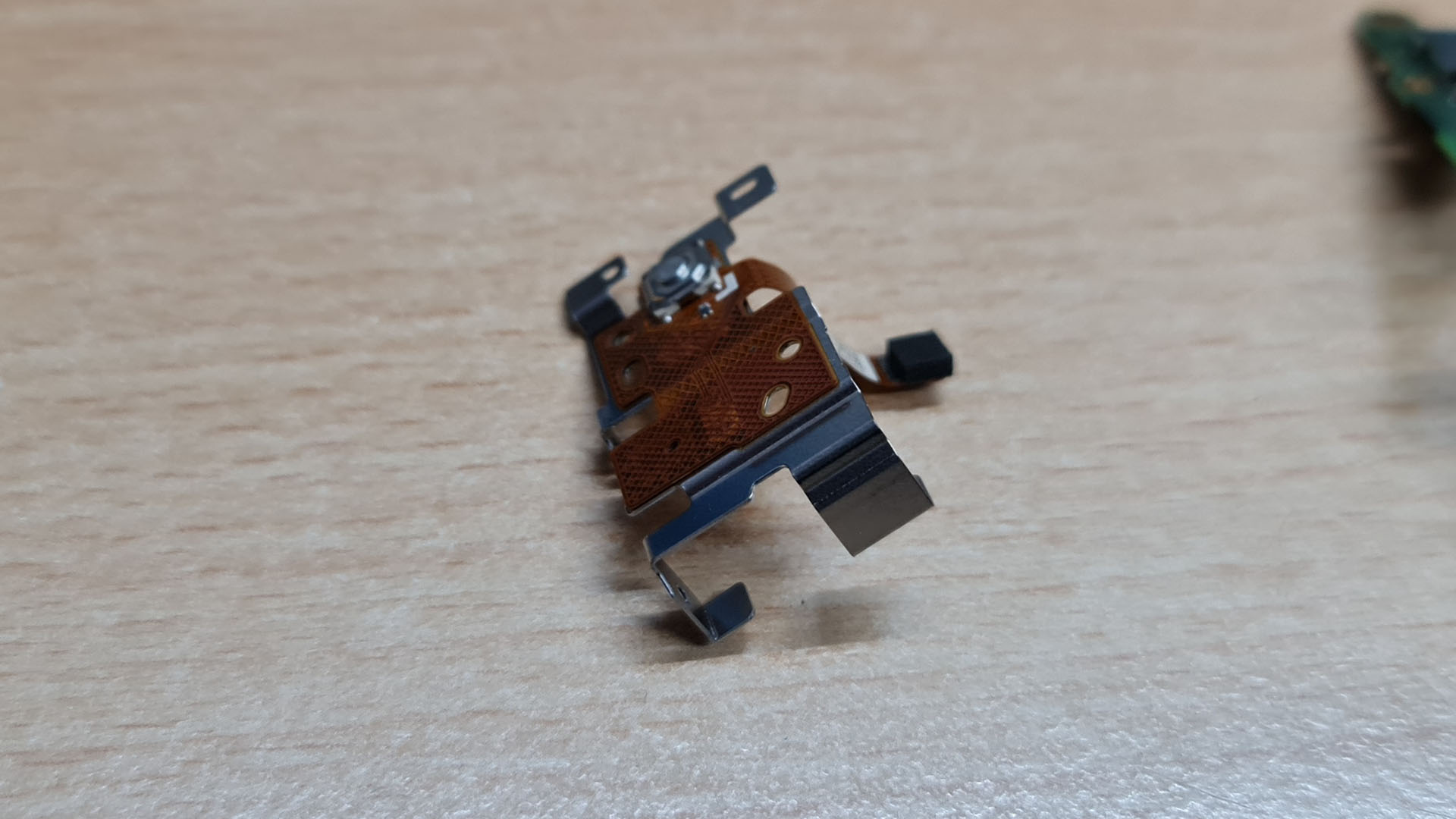
Also put this to the side.
Testing the parts
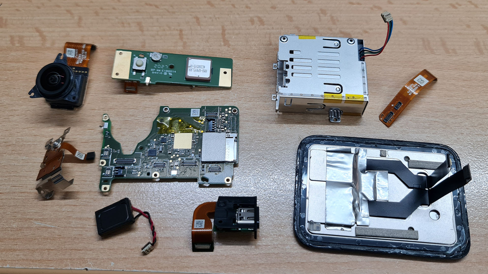
Now we have removed almost everything from the case. The whole back assembly with the screen, the battery casing, the GPS / button module, the lens module, the power button, the speaker, the USB connector and of course, the mainboard.
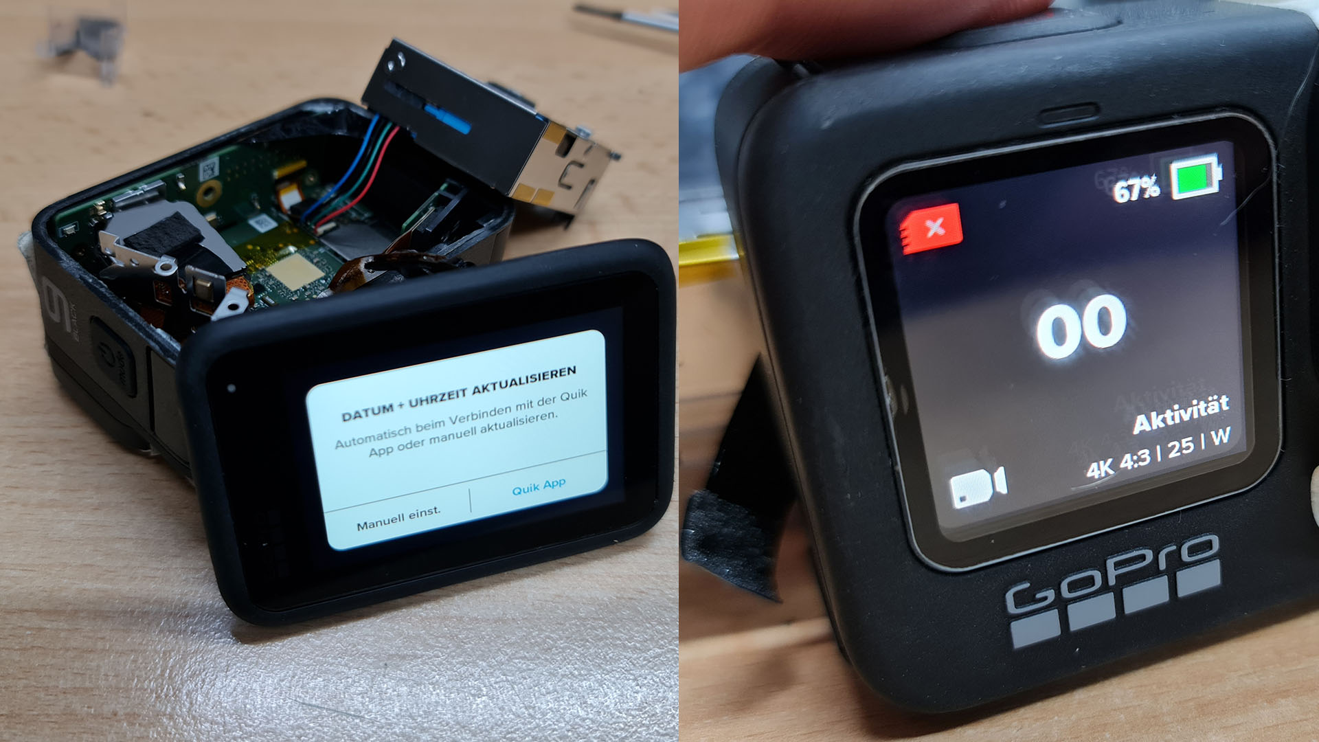
I took this opportunity to check if everything is still working by loosely reassembling everything in the case and to my relief it was still powering on and working as before. Please do not run the camera for longer periods in this state at it might overheat the wifi module because currently it has no antenna attached!
Removing the front screen
For most use-cases this would be the extent that a stripping process would go to, you could probably already omit a few things, but there is still something that can be done. As i said in the beginning, i did this to help out a friend who wants to put this GoPro into a NamelessRC case. And that case has the option to include the front screen.
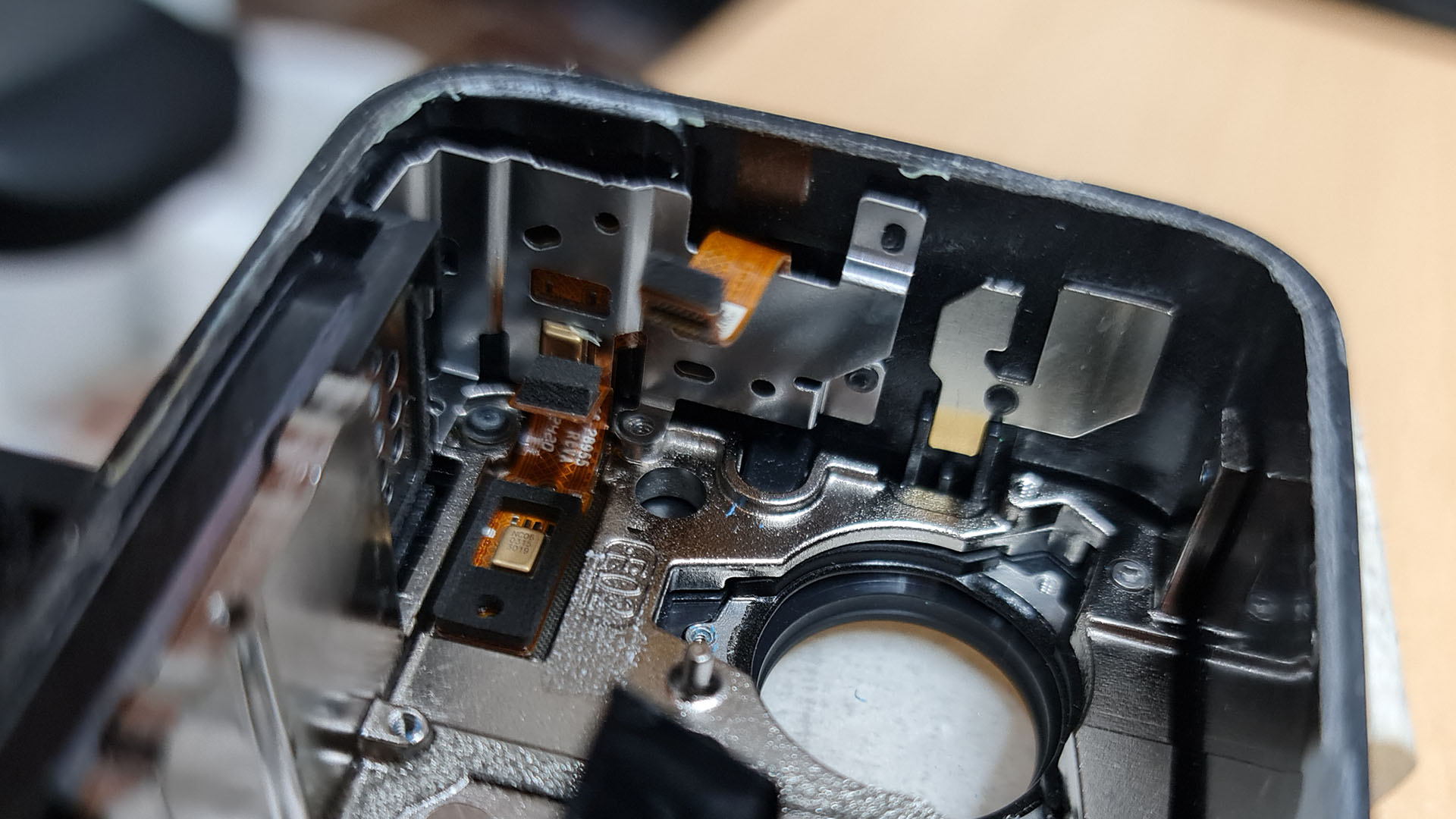
Unfortunately the front screen is sandwiched between the metal frame and the plastic cover of the front. That makes it seemingly hard to reach. But as it turns out, its not hard at all.
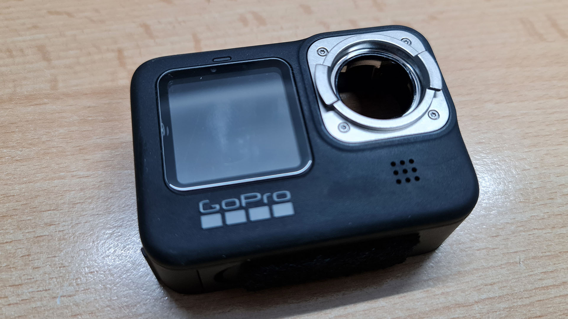
If you turn the camera around and take a look at the lens, with the lens cover removed, housing you can see four screws. Unscrew them. I am not quite sure what size they are but a 0.9 HEX worked.
On the inside, in the top left corner there is another screw of the same size.
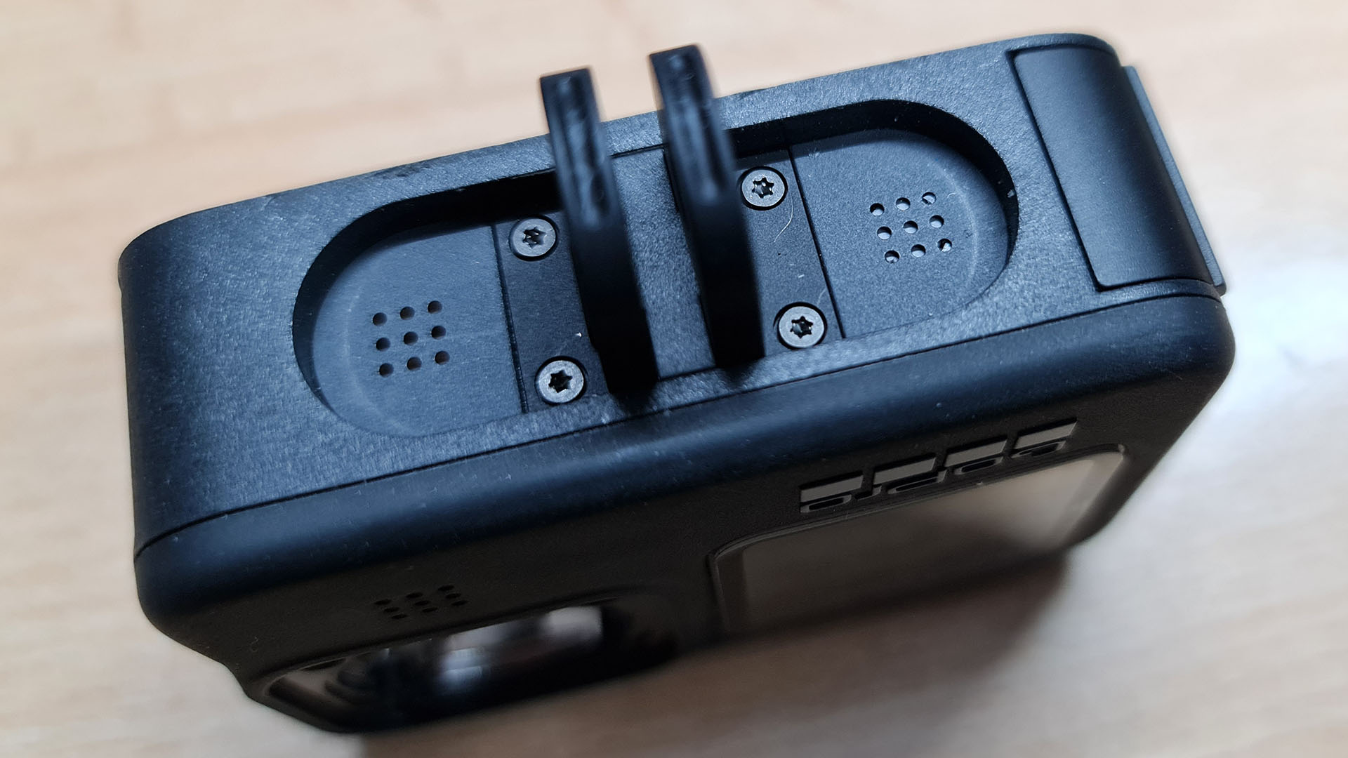
If you have not already done it, remove the foldable mount at the bottom of the camera, it is held by four TX5 screws.
You can take your prying tool and, from the front of the case, trough the lens hole, start pushing on the metal frame gently. It is only held in by plastic pins which will pop off. If they are stubborn, you can use a sharp tool or a dremel to remove the melted plastic dots that hold it down.
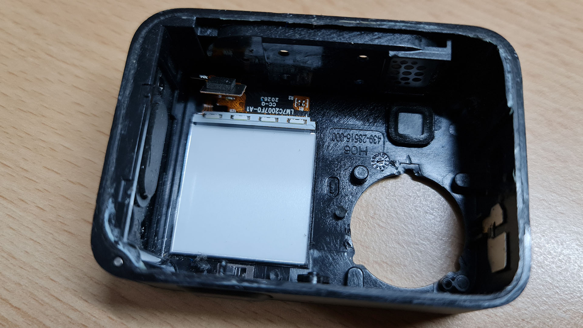
Now you can extract the screen. But be very careful as it is not protected by anything else. There is some adhesive but with some gentle prying from the bottom, NOT ON THE GLASS EDGES!!!!, it will come out. It is comprised of multiple layers and should be handled with a lot of care!
Curiously, after removing the screen there is a shiny mirrorlike surface visible where the screen was. This looks an awful lot like the plastic housings these screens useually come in (Hint: It probably is!). Thats why i decided to also remove it.
With a little bit of gentle heating you can carefully pry it off. Be aware that the whole metal brace is a heat sink so it will spread the heat fast and you might burn yourself. Once it is heated, use something flat to pry it off carefully. A hobbyknife works well.
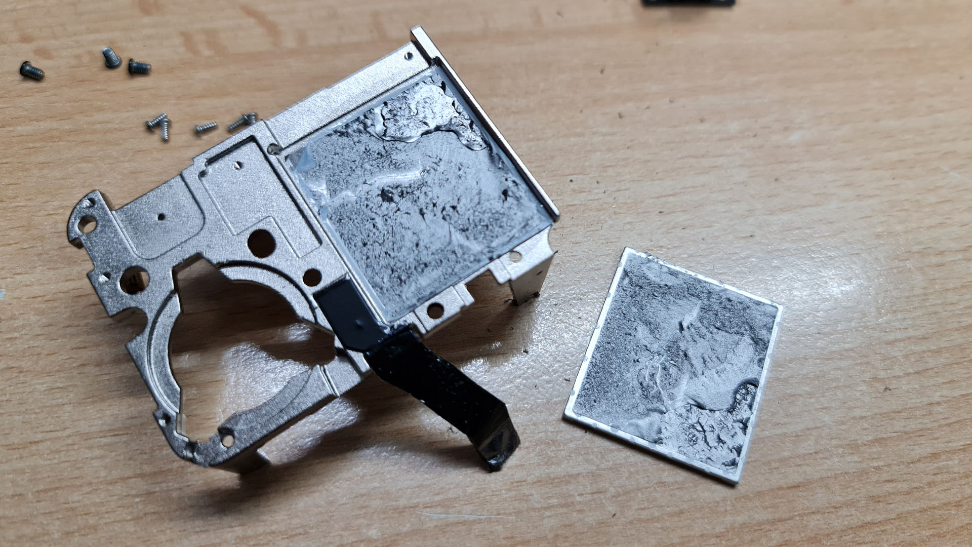
Underneath it you can find another of those graphite filled thermal conduction chambers. Despite its messy look it does not leave stains. I brushed it off with a paper towel and it did not leave a mark.
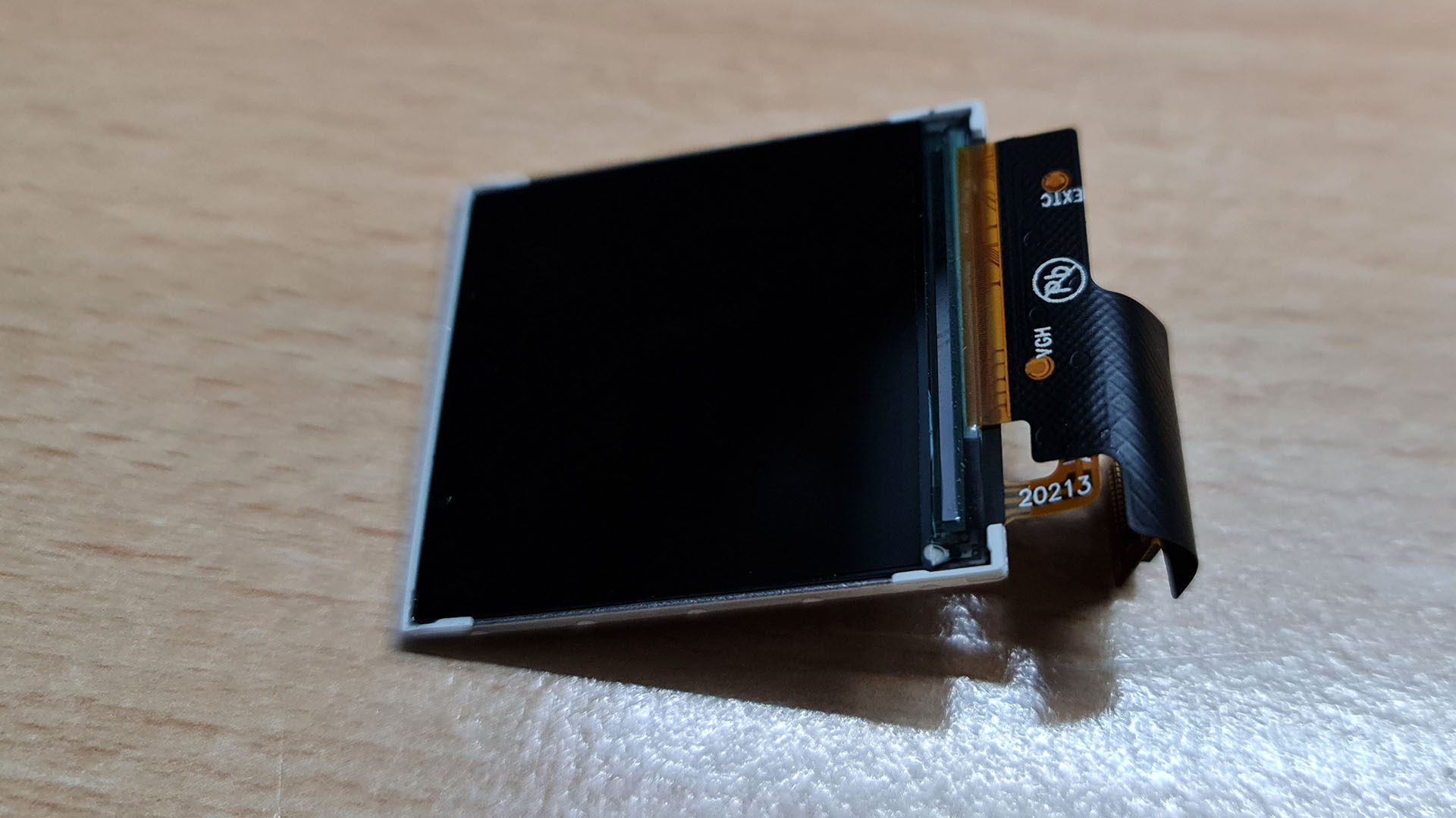
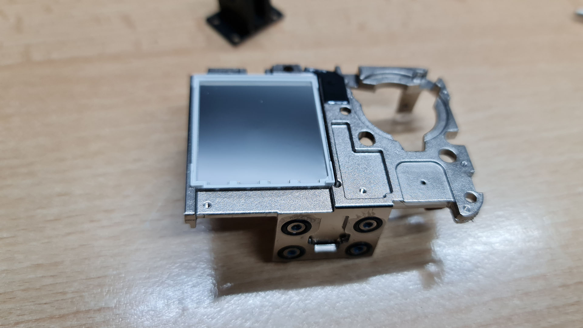
Having this piece off and put back onto the screen it looks more like the lcds i know. I am pretty sure it is better to have it on.
Adding a WiFi antenna
Before installing it into any case, consider adding a wifi antenna. Without an antenna the signal can go nowhere and it will heat up the wifi hardware and potentially burn it out! Also without an antenna you will not have a lot of range.
For this i used a coax wire which i salvaged from a broken antenna. For the 2.4 Ghz range it should have an exposed length of 31 mm. If you use a shielded wire, solder the shielding to a ground pad on the mainboard.
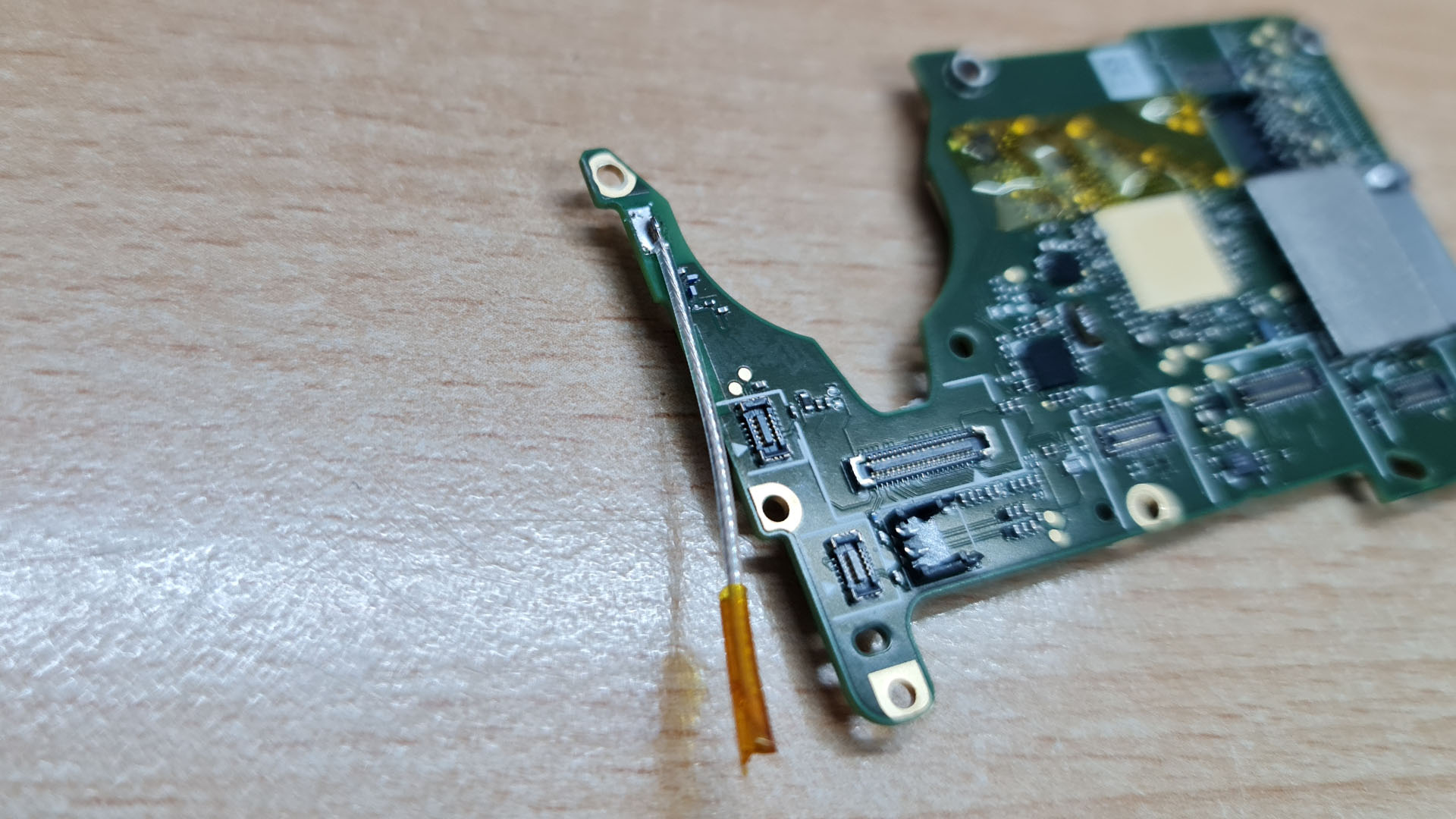
I attached the antenna wire at the position of the spring connector that made the wifi connection with the housing (It can be desoldered easily.). If you use a shielded wire you can use this position and the ground pad around the screwhole above it to connect the wifi antenna. I added a piece of kapton tape at the end of the antenna to make sure that it does not cause any shorts.
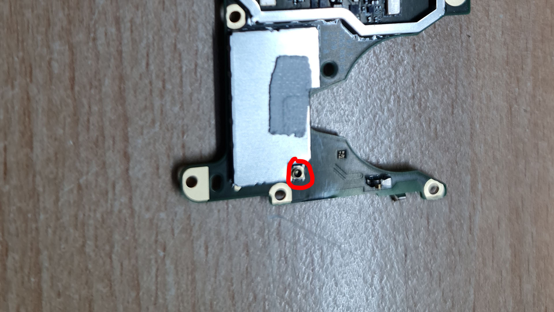
I did notice that there was a small connector on the antenna path but i was not quite sure how it was connected and therefore did not use it.
The extraction process is now complete and the camera is ready to be transplanted into a new case. If you do not use the NamelessRC case you can now stop reading this article and take a look at the instructions for your case!
GoPro mounting into NamelessRC Case
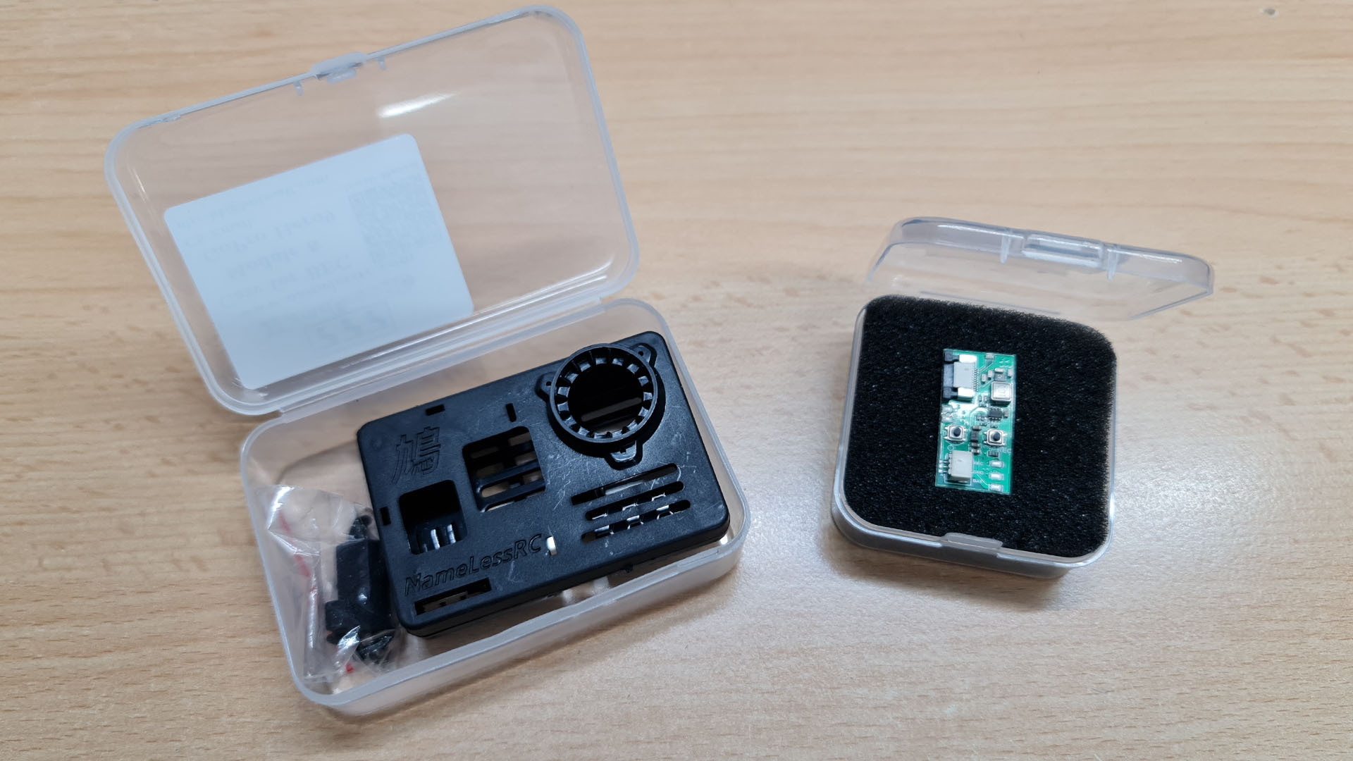
The NamelessRC case is basically just an extension for the NamelessRC BEC which is a really nice little pcb to help working with your naked GoPro! Both items come in their own little pastic box to keep everything neat and tidy.
Lets take a quick look at what we will need for the rest of the process.
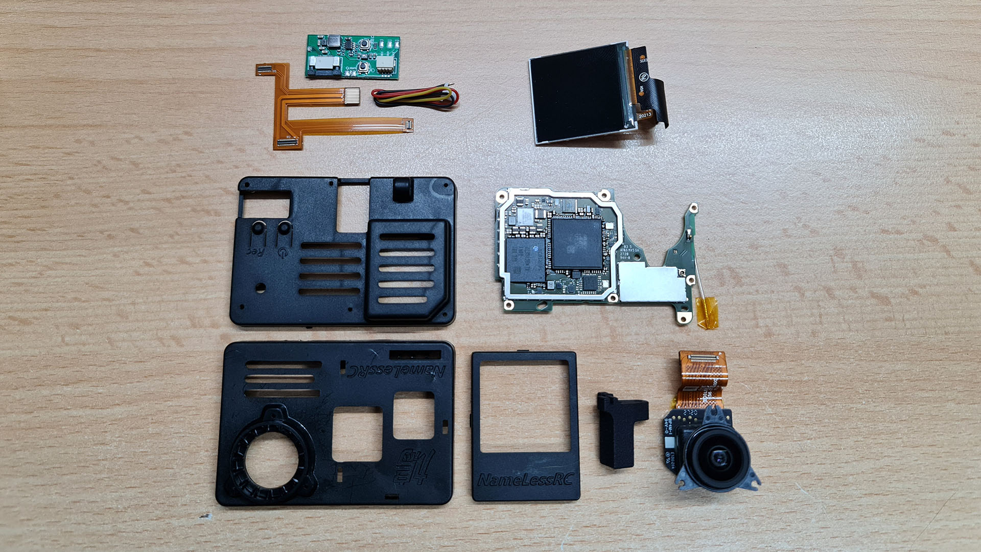
On the picture you can see theThe three parts of the case in the lower left. If you do not want to use the front screen simply put the small frame away. In our case we want to use it.
In the top left you can see the BEC with its own little flex cable and a three pin connector that will go to your drone. On the top right is the front screen assembly. Below ist comes the mainboard and in the lower left corner you can see the lens module. Next to the lens module is a little plastic piece that comes with the case to offset the mounting point.
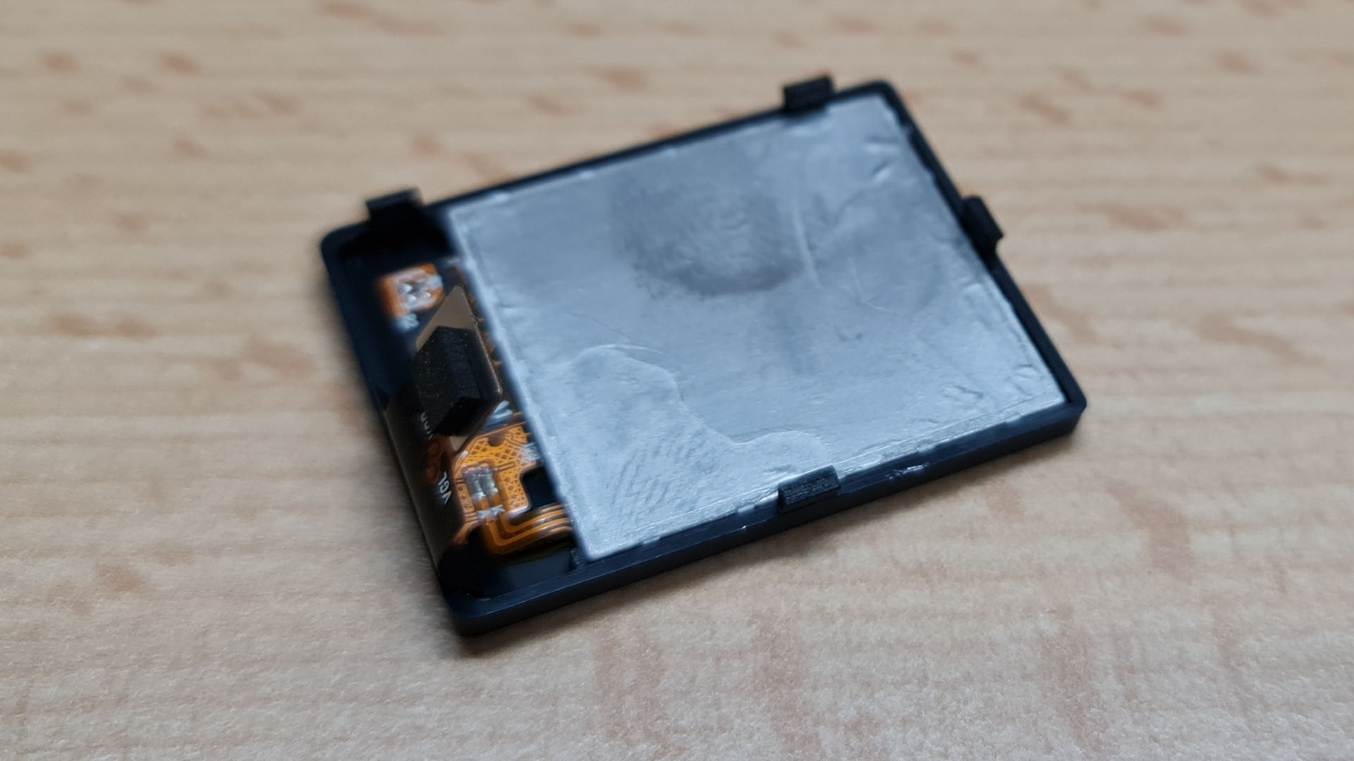
As we mentioned before, we will use the front screen. Just put the whole assembly into the small frame, it should fit snuggly. In the picture you can see the graphite layer on the back of the screen.

To mount it into the case, just click the four tabs into their slots. Be aware of the flex cable, do not damage it!
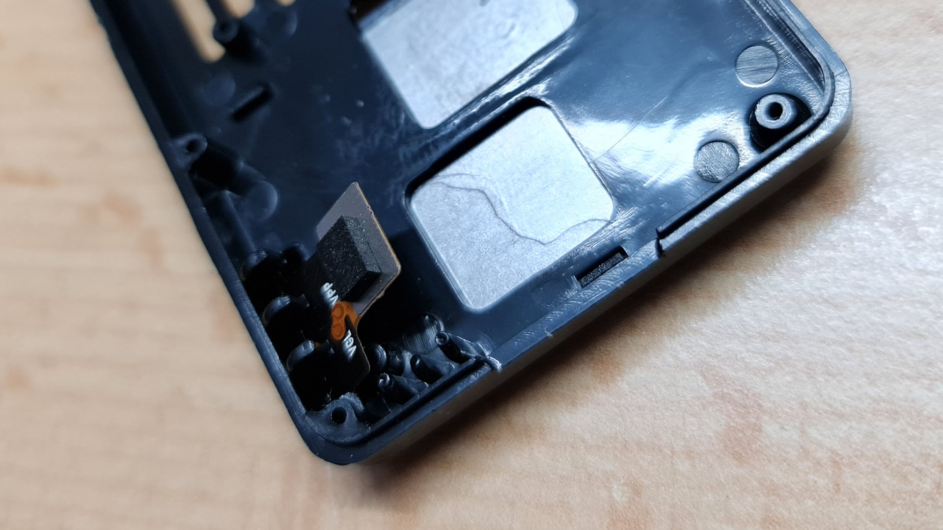
There is a slot in the front of the case to fiddle the flex cable through.
Now we will mount the lens module. Take a look at the position of the three mounting tabs and match them up with the screw holes in the case. Use three of the small screws which came with the case to secure it in place.
The mainboard is the next element which goes into the case. Again, it will be fixed with three of the same small screws. Use the top left, bottom left and bottom center holes to screw it in. Dont connect the lens module flex cable yet.
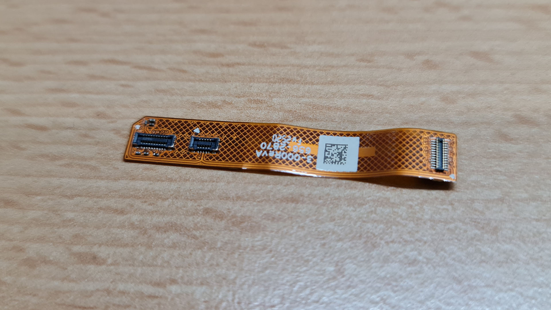
Take the flex cable which came with the case and plug it into the connectors for the GPS module and the back screen. The two longer tabs will show to the right.
Now we can mount the BEC into the case. Please note that there is some adhesive on the back. Remove the protective layer and align it with the plastic tabs in the lower right corner. Otherwise the buttons will not lign up with the back case.
You can plug in the other tabs from the flex cable into the BEC and into the connector for the power button. After attaching these two you can also connect the lens module to the mainboard.

Before we close the case you should check all connections once more to make sure that we will not have to open it up later to reseat a cable. The last step is to screw all the long, self-tapping screws from the back into the case.
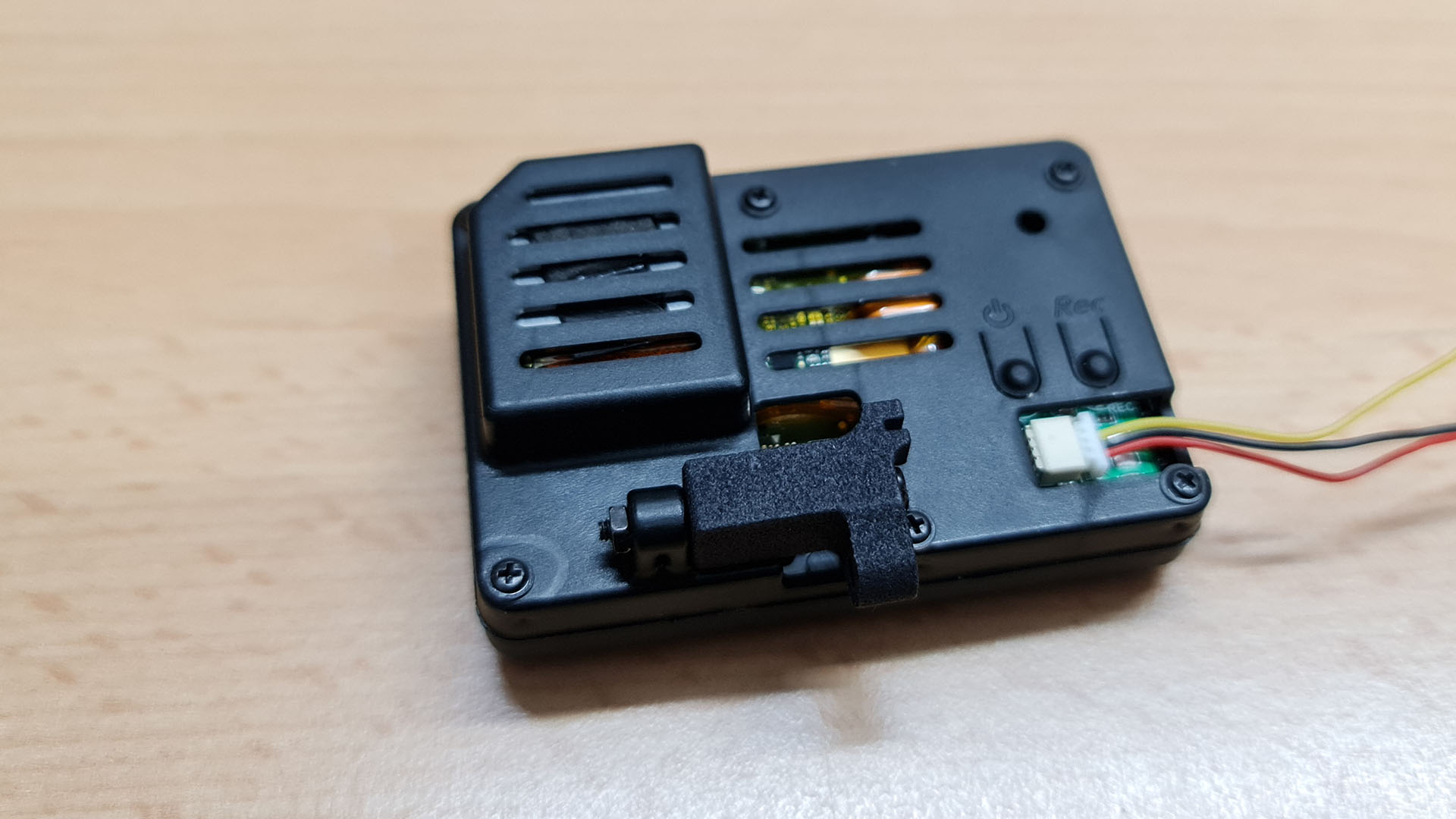
And this is how it should look. Notice the additional plastic piece that moves the mounting point over.
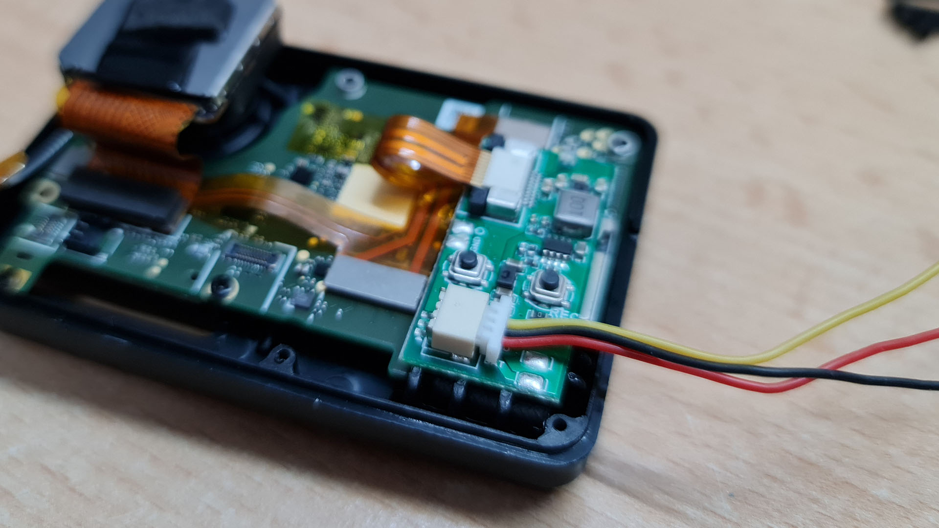
If everything went well, we should now have a working naked GoPro 9. With the included three pin cable it is fairly easy to check. Just solder a connector to the red (+) and black (-) cables and use a 2S LiPo pack to power it (Always check what voltage the BEC supports before you connect anything!).
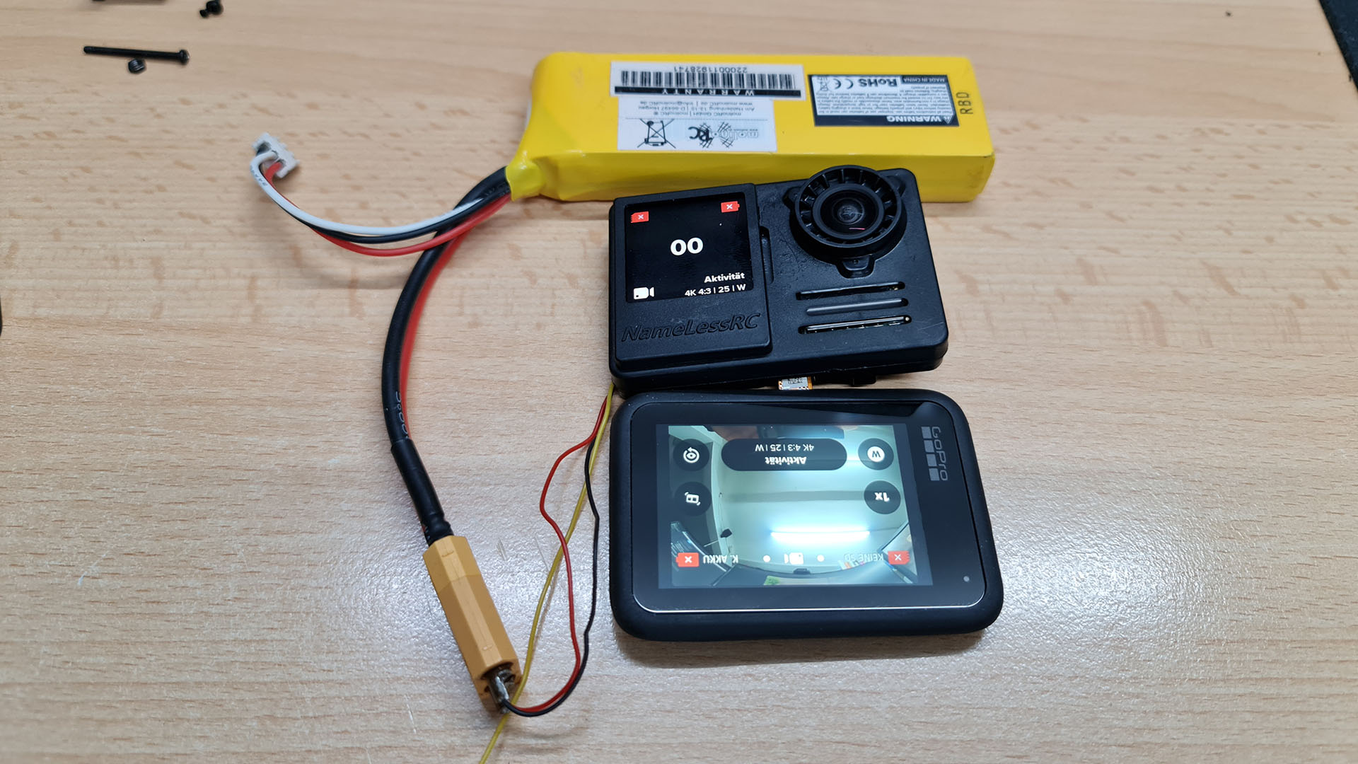
A quick test confirms it, everything went well, the camera does still power on and recording still works!
This concludes the article. If you try anything that is described here, please be aware that you do it at your own risk!
If you have any questions or want to share your results, use the comment function!