Portable RGB Led Torch using Arduino
Sebastian Pohl - 1. August 2017
This project has been on my mind for a few years now. Since i had seen it somewhere i always thought about building one myself but unlike the one back then i wanted it to be portable.
The theory
Basically it is a crude 2d simulation of a fire.
There are some scripts and snippets on how to get a 1d fire simulation running on an arduino but my choice was to make it 2d with wrapping on one edge. It should be like a screen wrapped around a cylinder.
The easiest way was to interpret a longer rgb led strip as a matrix of leds. This picture might help to understand how it is working:
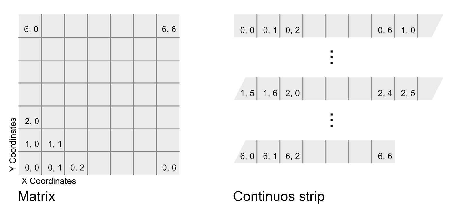
Instead of having a grid of leds i use a strip and partition it into „rows“ to build up the same matrix. The strip is then wrapped around a cylinder and now becomes the wrap-around screen that is needed.
For the fire effect i was aiming for a very basic approach. The bottom row of „pixels“ would get a certain amount of simulated heat that dissipates upwards. To keep the flames going the bottom row would get more heat in each simulation step. After each step of simulation all the cells would have a certain amount of heat that translates to a color. The more heat a cell has the brighter the color gets. Colder cells would be darker or off.
The software
Since my experience with arduino programming is very small (it comes down to an LCD Thermometer and using and arduino in my 3d printer) i started from the bottom and read a lot of basic stuff on how to program microcontrollers and did a few tutorials with blinking leds, rgb leds and other simple stuff.
My first idea was to do everything from scratch but i quickly found the FastLED library and decided to ommit writing my own rgb-led-strip controls. It comes with a lot of examples and i based my own code of off their DemoReel100 example.
This is my full code:
#include "FastLED.h"

FASTLED_USING_NAMESPACE

// Basic definitions of the led strip and coomunication
#define DATA_PIN    3
#define LED_TYPE    WS2812B
#define COLOR_ORDER GRB

// Some more definitions the define our virtual pixel grid
#define NUM_LEDS    60
#define IN_ROW 5
#define ROWS 12

// The one-dimensional array of leds
CRGB leds[NUM_LEDS];

// A two-dimensional array to store the temperatures for each led
int positions[ROWS][IN_ROW];

// The maximum brightness
#define BRIGHTNESS          40
// The refresh rate
#define FRAMES_PER_SECOND  30

/* Ignition and dissipation are used by the fire simulation.
 * Ignition determines if more heat is added at the bottom.
 * Dissipation is the amount of heat that can be lost each step for a cell.
 */
#define IGNITION 127
#define DISSIPATION 80

// The color palette
CRGBPalette16 gPal;

void setup() {

  // Allow a few seconds for recovery
  delay(3000);
  // Tell the library how the strip is configured
  FastLED.addLeds<LED_TYPE,DATA_PIN,COLOR_ORDER>(leds, NUM_LEDS).setCorrection(TypicalLEDStrip);

  // Set all the cells to 0 temperature
  for ( int i = 0; i < ROWS; i++ ) {
    for ( int j = 0; j < IN_ROW; j++ ) {
      positions[i][j] = 0;
    }
  }

  // Set the maximum brightness for the strip, useful to controll the overall energy consumption
  FastLED.setBrightness(BRIGHTNESS);

  // Choose the palette. HeatColors_p goes from red over yellow to white.
  gPal = HeatColors_p;
}

void loop()
{
  // Make the random more random
  random16_add_entropy( random());
  // Simulate the fire
  fireLoop();
  // Show the result
  FastLED.show();
  // Wait ...
  FastLED.delay(1000/FRAMES_PER_SECOND);

}

/*
 * Troughout the function qsub8, qdd8 and random8 are used to prevent overflow over 255 and to speed things up.
 */
void fireLoop () {

  /*
   * First we have to loose some temperature. If we only added more in each step
   * the torch would be at full brightness after just a few cycles.
   * It is separated into two options.
   * The bottom row dissipates less energy so the flame keeps on burning.
   * The other rows randomly loose temperature. The higher the row is, the more
   * temperature is lost.
   */
  for ( int i = 0; i < ROWS; i++ ) {
    for ( int j = 0; j < IN_ROW; j++ ) {
      if ( i == 0 ) {
        positions[i][j] = qsub8 ( positions[i][j], random8(2, 6));
      } else {
        positions[i][j] = qsub8( positions[i][j],  random8(0, DISSIPATION) + ( random8(0,7) * i ));
      }
    }
  }

  /*
   * Heat is moving upwars so we are checking from the top down if there is heat in the cells below
   * and transfer it up.
   */
  for ( int i = ROWS - 1; i > 0; i-- ) {
    for ( int j = IN_ROW-1; j >= 0; j-- ) {
      positions[i][j] = qadd8(positions[i][j], positions[i-1][j] / 3);
    }
  }


  // If we have ignition, more heat is added in the bottom row at a random position.
  if( random8() < IGNITION) {
    int x = random8(IN_ROW);
    positions[0][x] = qadd8 (positions[0][x],  random8(40, 60));
  }

  /*
   *   When all calculations are done, each led is assigned a color according to its temperature.
   *   As i did not like the full white for the maximum temperature it is scaled back to 0 .. 150
   *   which keeps it in a nice red to warm yellow/orangy tone.
   */
  for ( int i = 0; i < ROWS; i++ ) {
    for ( int j = 0; j < IN_ROW; j++ ) {
      byte colorindex = scale8( positions[i][j], 150);
      CRGB color = ColorFromPalette( gPal, colorindex);
      leds[i * IN_ROW + j]=color;
    }
  }
}
This is not entirely my own code, i watched a lot of tutorials on how to do simple 2d fire simulation and even found a few examples of code on how to do 1d fire simulation with a led strip.
It might not be the most perfect way but it works and looks decent.
Feel free to ask any question about the code in the comments below!
The hardware
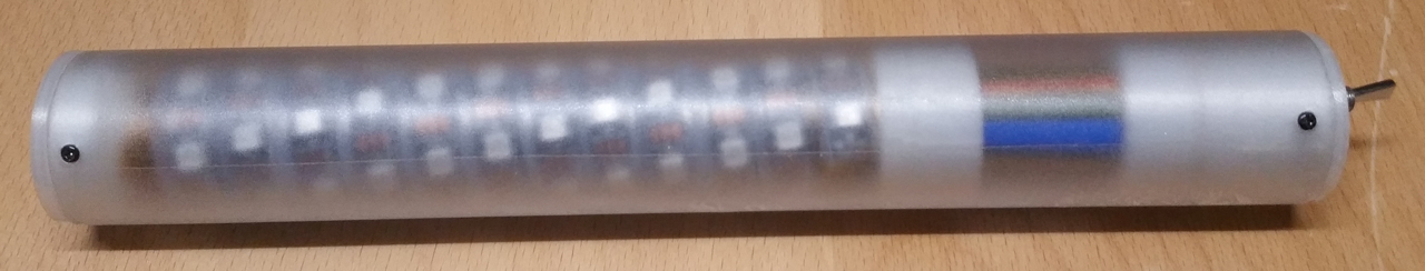
The trickier part was to get the right hardware for the project. I wanted a clean, nice look for the finished product. I finally settled for a 40mm acrylic tube with a few 3d printed parts to hold everything in position inside.
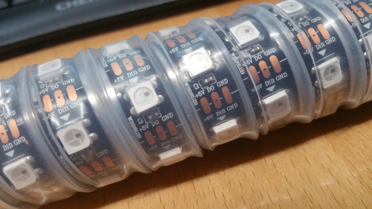
But let me start from the beginning. I had a sunfounder raspberry pi kit on my desk for some time now. It has a lot of stuff like leds, displays, sensors and some other stuff in it. Usually to play around with the raspberry pi. I somehow got a free arduino UNO and started playing around with the stuff on a breadboard. I then decided to buy the cheapest ws2812b strip i could get on amazon and started to test if my idea could work.
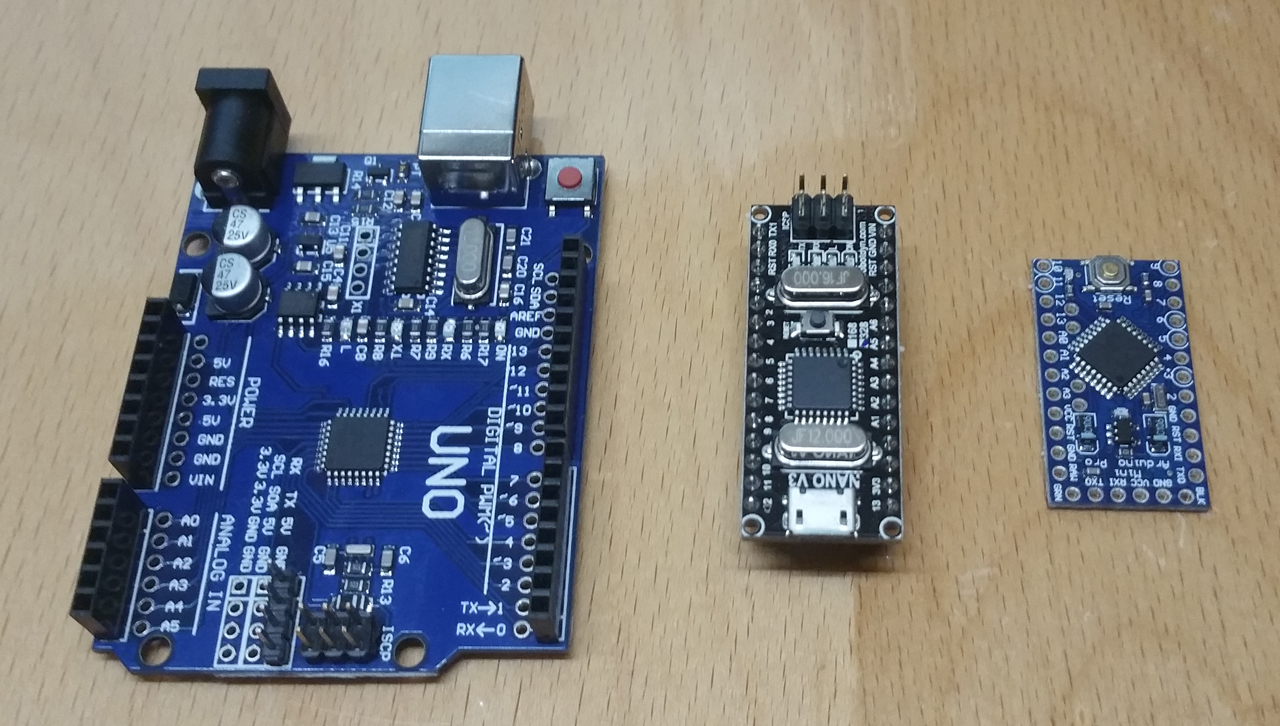
First tests with the UNO looked promising and the led strip wrapped around a metal tube (i had one on my desk, i do not know why…) looked great, too.
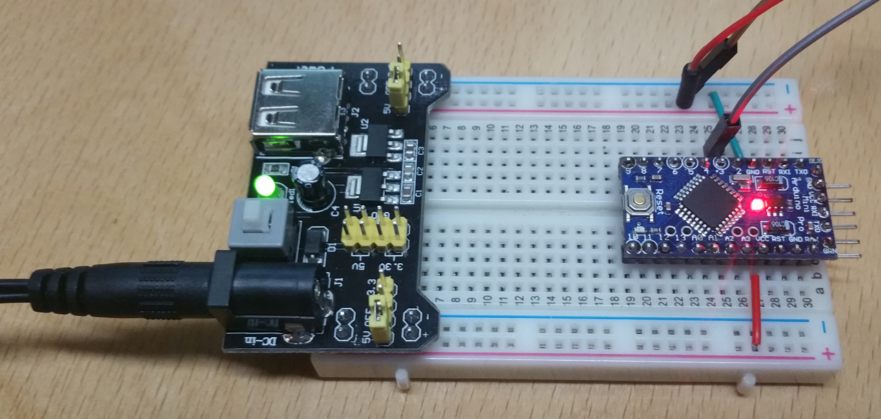
I moved from there to the arduino pro so i could fit it inside the metal tube.
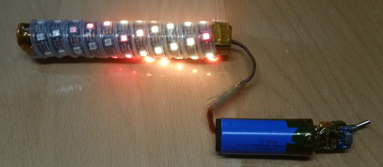
From the start i was looking for a convenient way to power the whole thing without making it too bulky. I calculated that i needed almost 2A to light up all 60 leds at 100%. I found this powerbank on amazon and bought it. But it refused to power the torch. Possibly because the power consumption when starting was not high enough to trigger the circuit to allow it to draw the full 2A.
I fixed this problem by ripping out the original circuit from the powerbank and adding this one. It does not have a cutoff and i still can charge the massive 26650 cell from usb. It even has a convenient indicator that makes the bottom part of the torch glow green to let you know when it is fully loaded.
Adding a switch to cut off power was the final step for the power supply.

The next part in line was the microcontroller. It soldered the usual pin headers to it and the 90 degree connector to have access to the programming header for reprogramming it later. To prevent any damages or short circuits i wrapped it in heat shrink tubing . The final part has a power connector on the one end and the 3 pin connector for the strip on the other end. I added a small capacitor to help smooth out the voltage (I am not sure on how this works in detail or if it is really necessary but i read it somewhere that it might be a good idea…).
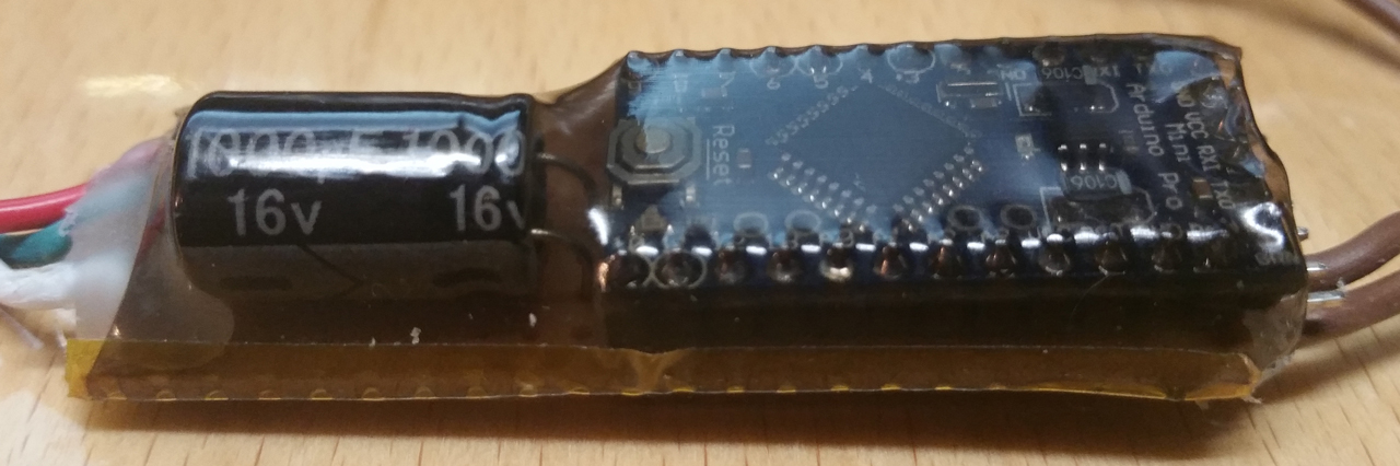
If i get too excited i sometimes forget to test in between each step to make sure it is still working…
To get it to fit inside the 40mm acrylic tube i made some 3d printed parts to keep everything in place.

And after some trial and error i got everything to fit inside the tube. Here is an overview over the finished inner parts.
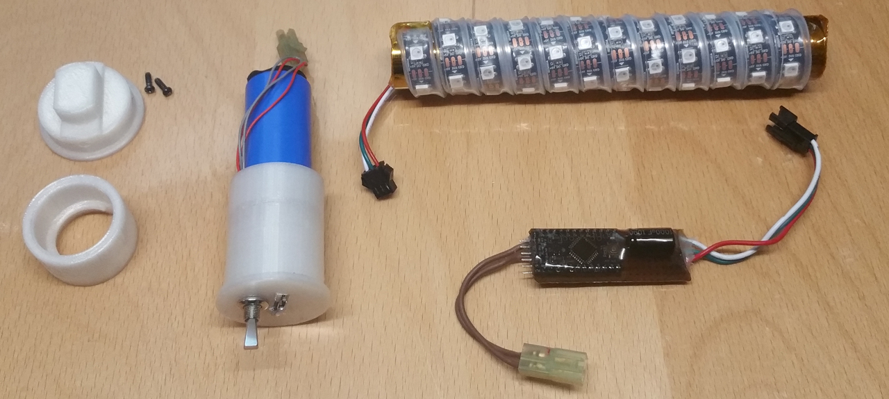
I really like to keep things modular. In every of my DIY projects i try to avoid things like superglue and hotglue because it makes things permament. If i decide to change this or that later on i will have to use force to pry things apart. So i prefer to have things screwed together or press-fit so i am still able to disassemble everything if i have to go back and change something.
And like almost every other DIY project i have tons of parts left over to play around with. Any ideas for the next project? 🙂
Ein Gedanke zu „Portable RGB Led Torch using Arduino“